


3
Chapter 2 Theory of Operation
Description of
Operation
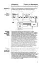
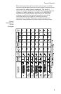
Figure 2 is a block diagram of the major functional parts of
the Model 4391A RF Wattmeter. The Microcomputer
integrated circuit shown, controls all the other portions of
the instrument, which fall into two major groups.
Keyboard,
Range
Switches, and
Display
Group
The keyboard and range switches serve only to pass
information to the computer. The display, of course, returns
information from the computer to the operator. The display,
which is comprised of four seven-segment LED digits, is
strobed digit by digit left to right at a rate of approximately
one digit per millisecond. This serves to conserve battery
power and drive circuitry while providing scanning for the
columns of the keyboard. Each time a digit is strobed, the
corresponding column of the keyboard is read and if a key is
pressed, the computer puts the code for that key into a
memory cell. The nine mode keys select which parameter is
to be measured. The three modifier keys simply modify the
way in which the result is displayed. The range selector
switches identify to the computer the nominal full scale
values of the elements used. They have no effect on input
sensitivity, which is determined by the elements.
Elements,
Analog
Circuitry, and
A/D Converter
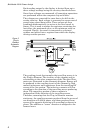
These components are controlled by the computer. The Plug-
in Elements in the line section provide low level positive
voltages related to the instantaneous value of power (see
Figure 3). The first group of solid state switches selects the
forward element, the reflected element, or ground as the
input to the preamplifier which boosts these signals to 0.1 to
2.0 volt range. The remaining switches shown as two groups
direct the output of the preamp to the analog-to-digital
converter either directly or through a peak or negative peak
detector. The analog-to-digital converter converts the voltage
to a 15 digit binary number.
Figure 2
Circuit Block
Diagram