


Maintenance
27
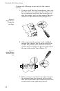
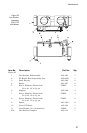
Line Section
Removal
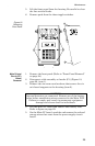
1. Remove the QC connectors (page 26).
2. Remove the four screws and lock washers that secure
line section assembly to the housing (item 3).
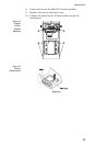
3. Using minimum pressure, spread apart the sides of the
lower housing assembly just far enough to allow the line
section assembly to be removed.
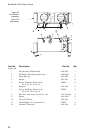
To remove the line section PCB, continue with the next
steps.
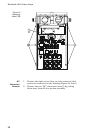
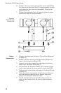
4. Remove the two screws (units with serial numbers 1723
and below) or the two hex nuts (units with serial
numbers 1724 and above) (Figure 21, item 5) that secure
the PCB cover then remove the cover (item 6) and
spacers (item 7).
5. Disconnect the ribbon cable assembly from the PC board
header (J1).
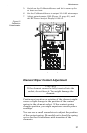
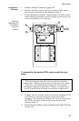
Figure 20
Removing QC
Connectors
and Line
Section
CAUTION
This instrument contains static sensitive electronic
components. Before opening or servicing the unit, make
sure that you understand and practice electrostatic
discharge component handling. Failure to comply may
result in permanent damage to sensitive components.