


Bird Model 4391A Power Analyst
8
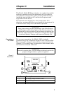
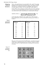
Connections The Model 4391A contains a short section of rigid 50 ohm
coaxial air dielectric transmission line. To make
measurements relating to the travelling waves in a coaxial
line, that line must be disconnected at some convenient point
to permit the Model 4391A air line to be inserted.
Although the Model 4391A is normally supplied with two
Female N-type connectors, a variety of easily
interchangeable connectors are available to facilitate
connecting to the user’s system.
Once the Model 4391A is installed in the coaxial line, a Plug-
in Element or a pair of Plug-in Elements must be selected
which correspond to the frequency and power levels to be
measured.
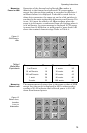
NOTE: The instrument is shipped with dust plugs
installed in the element sockets. Remove the dust plugs
to insert elements.
In order to take full advantage of the Model 4391A’s
capabilities, two elements in a 10:1 ratio of power range
should be used. If only one element is used, the other socket
should be filled with a dust plug or a higher power element.
Also, for greatest accuracy, the element(s) should be chosen
having the lowest possible power range that will not result
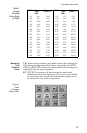
in over-ranging. Table 1 lists elements required for each
mode of operation.
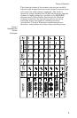
Table 1
Plug-In
Elements
Required
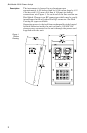
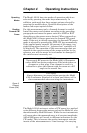
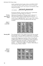
The higher power element is placed in the socket marked
“FORWARD” and its arrow pointed in the direction of
forward power flow (toward antenna or load). The lower
power element is placed in the socket marked
“REFLECTED” and is normally pointed in the direction
opposite to forward power flow. The elements are clamped in
place by the hold-down catches on the face of the line section.
These catches must be used to avoid error due to the element
not contacting the bottom or seating plate of the socket. With
the element(s) in place, set the range switches to correspond
Mode Forward Reflected
FWD CW
RFL CW
SWR
*
* The reflected element must have a nominal power range
one tenth that of the forward element.
FWD PEP
RFL PEP
% MOD
FWD dBm
RFL dBm
RTN Loss
*