


Maintenance
25
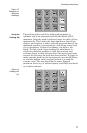
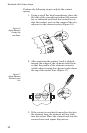
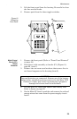
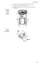
5. Lift the front panel from the housing. Be careful to clear
the line section blocks.
6. Remove pads from the three toggle switches.
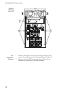
Main Printed
Circuit (PC)
Board
Removal
1. Remove the front panel (Refer to “Front Panel Removal”
on page 24)
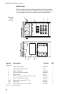
2. Disconnect cable assembly at header (P1) (Figure 19,
page 26, item 1).
3. Remove the six screws and washers that secure the cir-
cuit board supports to the housing (item 2).
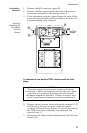
4. Lift the Main PC board and remove one battery tube.
Refer to figure on page 29.
5. On the Main PC board, unsolder and remove the red and
orange wires that come from the power supply circuit
board.
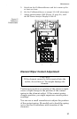
Figure 18
Removing
Front Panel
CAUTION
Internal batteries are connected. Remove one of the battery
tubes before unsoldering wires connected to the Main PCB.
Failure to comply may result in permanent equipment
damage and severe shock to individuals.