


Bird Model 4391A Power Analyst
16
Insertion
Loss or
Attenuation
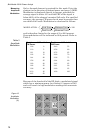
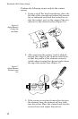
Attenuation or insertion loss can be measured directly using
an external single port line section (P/N 4230-006-1), a dc
feed-in adapter (P/N 4381-050), and a dc cable (P/N 3170-
058-6). The Model 4391A is inserted at the source end of the
device being measured. The second line section is inserted at
the load end and its dc output is routed by the dc cable to the
adapter inserted in the REFLECTED socket of the Model
4391A. Both elements are in this case pointed in the
direction of forward power flow. If the two elements do not
have a ten to one ratio, a correction factor must be added to
or subtracted from the “return loss” reading see Table 6,
depending on the ratio of the elements.
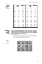
Table 5
Correction
Factors
Monitoring
Maximum and
Minimum
Readings
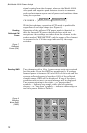
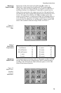
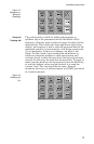
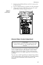
While operating in any of the modes described, the Model
4391A will continuously keep track of the highest and lowest
reading obtained. This action begins after ten reading cycles
to allow time for the peak detectors to settle from the
previous mode. To recall the maximum or minimum reading,
depress and hold the MAX or MIN key. When these keys are
released, the meter goes back to displaying the current value
of the parameter being measured. Recalling max or min does
not stop the meter from continuing to monitor the current
value and updating the minimum and maximum registers.
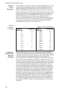
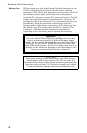
To clear the minimum and maximum register, the mode key
must be pressed again or a new mode selected. For example,
if CW power deviations are monitored, the Model 4391A is
installed as described at the beginning of this section and
turned on, then the power source is turned on and allowed to
stabilize. Once the system has stabilized, press FWD CW to
clear the MAX and MIN registers. At any time during test
the MAX and MIN keys can be used to recall the maximum
and minimum values without affecting the test. However,
pressing the FWD CW key or changing modes will clear the
registers.
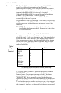
Table 6 Correction Factors
Ratio of
Elements
Added dB Ratio of
Elements
Added dB
1:1 –10 100:1 10
2:1 –7 200:1 13
2.5:1 –6 250:1 14
4:1 –4 400:1 16
5:1 –3 500:1 17
10:1 0 1000:1 20
20:1 3 2000:1 23
25:1 4 2500:1 24
40:1 6 4000:1 26
50:1 7 5000:1 27