


Bird Model 4391A Power Analyst
4
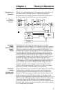
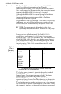
Each reading output by the display is derived from up to
three voltage readings using the circuitry described above.
Once these voltages are measured, all remaining operations
are performed within the computer chip as follows:
The voltages are corrected for error due to dc drift in the
analog circuitry. Each voltage is converted to square root of
power using stored data tables. These values are then
combined mathematically to arrive at the final result in
binary. This is used to update the registers containing the
last value, the maximum value, or the minimum value as
required. Finally, the result is converted to a decimal
number and placed into a register from which the display
driving routine operates.
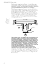
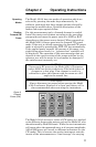
The coupling circuit that samples the travelling waves is in
the Plug-in Element. The circuitry of the element and its
relationship to the other components of the Thruline Watt-
meter are illustrated in the schematic diagram. Energy will
be produced in the coupling circuit of the element by both
mutual inductance and capacitance from the travelling RF
waves of the line section. The inductive currents will flow
according to the direction of the travelling waves producing
them. The capacitive portion of these currents is
independent of the direction of the travelling waves.
Therefore, assuming that the Plug-in Element remains
stationary, the coupling currents produced from the waves of
one direction will add in phase, and those produced from
waves of the opposite direction will accordingly subtract in
phase. The additive or “arrow” direction is assigned to the
forward wave.
Figure 3
Plug-In
Element
Schematic
Diagram