GB - 27
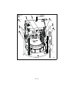
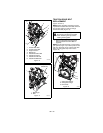
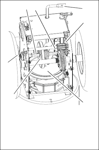
13. Insert new friction disc assembly into
frame. Install washers onto carrier
bearing and slide into speed selector
arm.
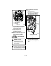
14. Slide hex shaft through new friction plate
assembly. Install pinion sprocket onto
hex shaft and slide shaft into right
bearing.
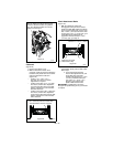
15. Install left bearing using hardware
removed in step 7.
16. Reinstall clip pin into hex shaft.
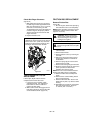
17. Connect pivot pin to speed selector arm.
See Speed Selector Adjustment on
page 21.
18. Install bottom cover.
19. Reinstall wheels.
20. Return unit to upright position.
21. Re-attach brush assembly to frame.
22. Connect spark plug wire to spark plug.
23. Adjust traction drive clutch. See Traction
Drive Clutch Adjustment on page 26.
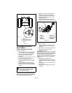
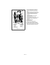
Figure 25
OS7142
1. Hex Shaft
2. Bearing
Flange
3. Speed
Selector Arm
4. Friction Disc
5. Spring Clip
6. Drive Plate
Assembly
7. Drive
Sprocket
2
4
1
5
3
6
7


