


GB - 22
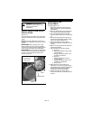
ATTACHMENT DRIVE BELT
REPLACEMENT
Remove Attachment Drive Belt
(Figures 15 and 16)
1. Shut off engine, disconnect spark plug
wire and allow unit to cool completely.
2. Remove the hardware attaching the
remote trigger cable to the brush
assembly.
3. Remove two screws securing belt cover
to unit and remove belt cover.
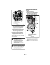
4. Remove belt finger by removing cap
screws mounting belt finger to engine
(Figure 16).
5. Remove attachment drive belt from
engine sheave (it may be necessary to
turn engine sheave using recoil starter
handle).
IMPORTANT: To avoid bending bottom cover,
when tipping unit apart, support handlebars
firmly and remove bottom cover by removing
six cap screws before separating unit.
6. Support frame and brush assembly.
7. Remove cap screws holding brush
assembly to frame (two on each side).
8. Separate assembly from unit. Lower
handlebar to floor.
9. Remove attachment drive belt from
lower pulley (hold brake away from belt).
Replace Attachment Drive Belt
(Figures 15 and 16)
1. Place new belt onto lower pulley and
while holding brake out of way, tip unit
together.
2. Secure brush to frame with cap screws.
3. Place belt onto engine sheave.
4. Replace belt finger.
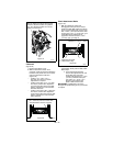
IMPORTANT: With the clutch lever engaged,
the belt finger located opposite the belt idler
must be less than 1/8 in. (3.18 mm) from the
belt, but not touching the belt, or belt
grabbing may occur causing brush to rotate
while the attachment clutch is disengaged
(Figure 17).
5. Adjust clutch (see Attachment
Clutch/Brake Adjustment on page 24).
6. Replace belt cover and secure with cap
screws.
7. Replace bottom cover and secure with
cap screws.
8. Reinstall remote trigger cable to brush
assembly.
CAUTION: Always support Sno-
Brush frame and brush assembly
when loosening the cap screws
holding them together.
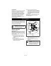
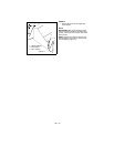
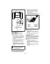
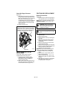
Figure 14
1. Shift Rod
2. Adjustment Pivot Pin
3. Speed Selector Arm
4. Hairpin
2
4
1
3
OS8060
-A--A-
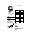
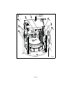
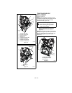
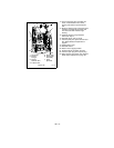
1. Brush
Assembly
2. Cable
Attaching
Hardware
3. Remote
Trigger Cable
4. Bottom Cover
5. Assembly
Bolt Holes
OS7242
1
2
3
4
5
Figure 15