


© 2005 Alamo Group Inc.
2-16
MACHETE
SERVICE BULLETIN No. 971404
Alamo Industrial Technical Services Department
1502 East Walnut
Seguin, Texas 78155
830-372-2708
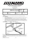
Restrictor Installation Lift & Dipper Cylinder Function:
Subject:
Lift and/or dipper functions drop to fast. When both functions are combined, sudden drop may
occur. Install one way restrictors in the dipper cylinder rod end port and the tilt cylinder barrel end port
of the control valve to prevent the sudden drop of the boom and damage to the boom and frame.
Service Required:
1. Remove the cover from the control valve, clean the control valve of all debris to prevent
contamination from entering system. Make certain that Boom is lower with head resting on the
floor. Make certain that all pressure is relieved from the system and all hoses.
2. Remove and plug the hose from the rod end of the dipper cylinder (Blue Tag) at the valve.
Remove the adapter from the valve.
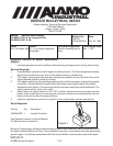
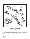
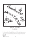
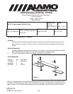
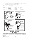
3. Install the new adapter (# 02972159), orifice plate and old adapter as shown in figure 1. Be
certain that the groove in the orifice plate is installed as shown. Perform the same procedure
to the barrel end of the lift cylinder valve port (Orange and White Tag)
4. Reassemble the machine and clean any spilled oil. Test for operation by running through its
cycle to remove any trapped air in system and inspect for leaks.
Parts Required:
Part No. Qty Description
02972159 2 Straight Adapter
02969398 2 Orifice Plate .055"
See Operators manual or Service Manual
for Port locations on valve if needed.
Models: Machete Boom Mowers
Date:
Apr. 14, 1997
Bulletin No:
971404
(Old # 970004A)
Parts:
100 % at Dealer Net
Labor:
1.5 hrs. at Dealer registered
Shop Rate
Termination Date:
Oct. 1, 1997
Old Parts Disposition:
No Returnable Parts
involved
Warranty Compensation will be provided following proper filing of warranty claim in accordance with
the Alamo Industrial Warranty Policy. Claim allowance may vary in accordance with laws governing a
specific region. Any Warranty associated with this service bulletin must be within authorized dates.
Figure 1
To Hose
To Valve
Orifie Plate
P/N 02969398
Note orientation
of notch in plate
Notch away from
valve
Existing
Adapter
New Adapter
P/N 02972159