


© 2005 Alamo Group Inc.
1-21
MACHETE
Information Bulletin 041797-1 Continued from previous Page
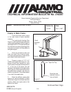
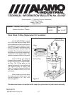
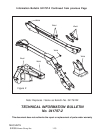
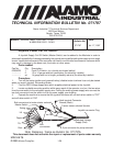
4. After aligning the Angles to Deck (See Figure 2) tack weld them in place. Recheck all
measurements and alignments, then weld in flanges in place.
TECHNICAL INFORMATION BULLETIN
No. 041797-1
This document does not authorize the repair or replacement of parts under warranty
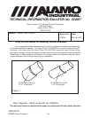
24-1/16" center
of hole to edge
12-1/16" center
of hole to edge
Reference Ribs
14--9/16" center
of hole to edge
Figure 2
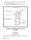
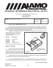
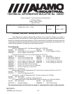
Figure 3
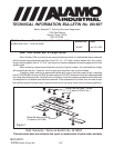
02892100
Bolt (8)
02971946
Flange (1)
00037200 Nut (8)
02971928
Hitch Post (1)
02972111
Flange (2)
02971946
Flange (1)
5. Clean all welds and area
around welds, remove weld
slag, burnt paint and etc. Re-
paint complete area around
flanges to prevent rust.
6.
Attach new Hitch Post
(02971928) to welded angles as
shown in Figure 3 using hard-
ware furnished with kit. Install the
Lock nut on top of the Hitch post
and the bolt heads down coming
up through the flanges, this will
give the maximum strength to the
bolts and Hitch components.
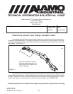
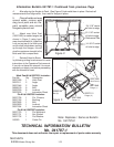
7. Reinstall Head to Boom
by following cutting head removal & install
instructions in the Operators Parts manual.
If you do not have this manual it is recom-
mended you obtain one before proceeding
with the reinstall of head.
Hitch Post Kit # 02972231 includes -
Part No. Qty Description
02971928 1 Hitch Post
02972111 2 Angle
02971946 2 Angle
02892100 8 Bolt
00037200 8 Locknut
02972232 1 Instruction Sheet
Pin Kit # 02967691 includes -
02971756 1 Pin, Chrome
02971746 1 Bushing
02970595 1 Bolt
00015800 1 Locknut
02971904 1 Instruction Sheet
Pin Kit # 02967687 includes -
02971720 1 Pin Weldment
02971701 1 Nut, Slotted
02971702 1 Flat Washer
165020 1 Cotter Pin
Note: Replaces / Same as Bulletin
No. 041797A1