Assembly Section 3-11
ASSEMBLY
SR20M/SR14M 10/03
ASSEMBLY
© 2004 Alamo Group Inc.
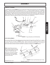
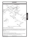
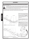
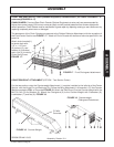
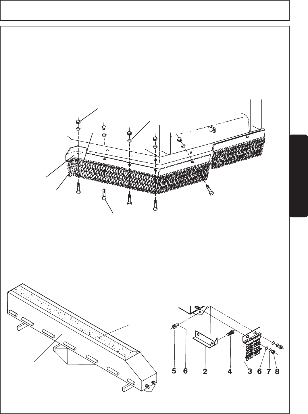
FIGURE 17. Front Chainguard attachment
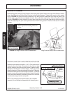
COUNTERWEIGHT ATTACHMENT (OPTION - Two Section Cutter)
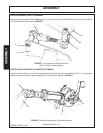
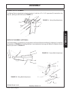
For the two section cutter the Counterweight Attachment (1) must be installed to the left side of the Center
Section with the Hinge Pin and Retaining Pin (Follow the Wing Attachment in this section). Fill the Counter
Weight completely FULL of Concrete FIGURE 18. Attach the Skid Shoe (2) to the Counter Weight with the
Bolt (4), Nut (5) and Washer (6). Attach the Chainguard (3) to the Counter Weight with Flatwasher (6),
Lockwasher (7) and Nut (8). FIGURE 19
Fill With
Concrete
1
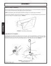
FIGURE 18. Counter Weight
FIGURE 19. Counterweight
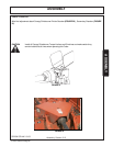
Chainguard Attachment
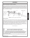
The placement of the Chain Guards corresponds to the Rubber Deflector Attachment with the exception of
the Front Center Section see FIGURE 17. Attach all Chain Guards with bolts and locknuts specified in the
parts list.
CHAIN GUARDS: Front and Rear Chain Guards (Optional Equipment at extra cost) are recommended for
higher than normal usage (100 hours or more per year) and will provide protection from thrown objects with
careful operation. Chain Guards must be maintained in good repair by replacing missing or worn sections or by
replacing completely when worn or damaged.
FRONT AND REAR DEFLECTORS (Standard Equipment) CHAINGUARDS ( OPTIONAL EQUIPMENT at
extra cost)(FIGURES 14-17)
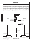
Attach chain bracket(1)
to center deck with
1/2" x 1-1/2" bolt
(2),locknut (3), and
washer (4) Individual
chain link (5) is held by
Chain Rod (6) see
FIGURE 17.
1
5
3
6
2
4


