


Assembly Section 3-12
SR20M/SR14M 10/03
ASSEMBLY
ASSEMBLY
© 2004 Alamo Group Inc.
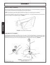
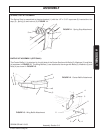
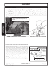
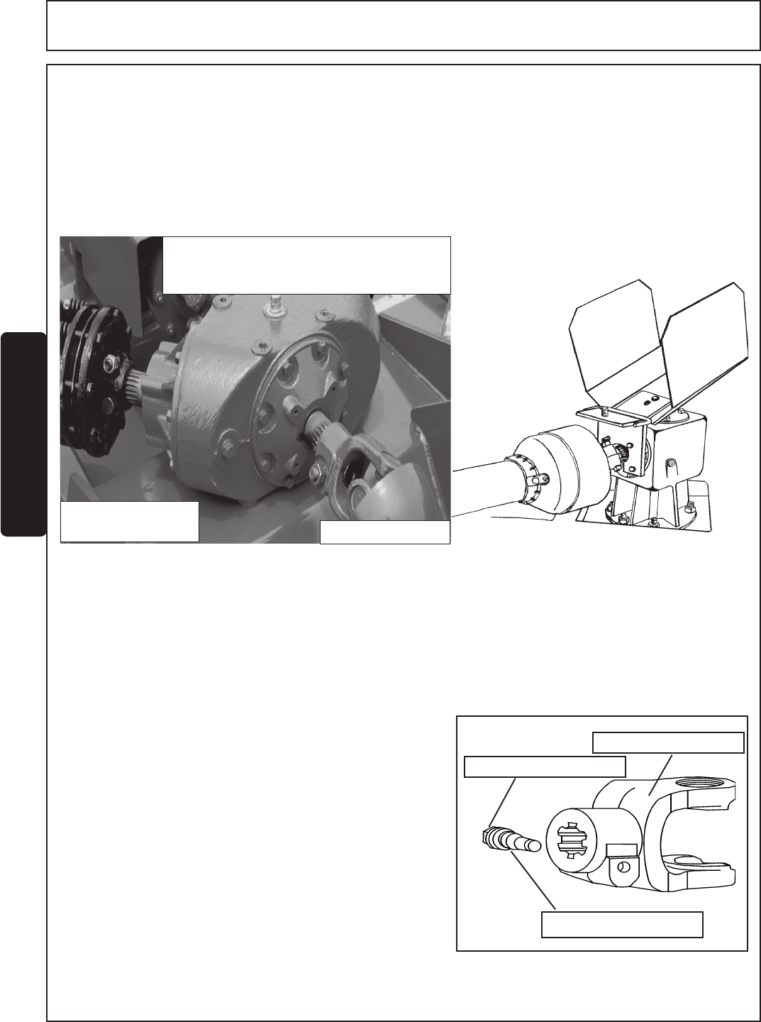
DRIVELINE ATTACHMENT
Remove Wing Nut holding Divider Gearbox Shield and raise Shield. Remove any tape from Gearbox shafts.
Attach the Slipclutch end of the Wing Driveline to the Divider Gearbox. Tighten bolts evenly to their proper
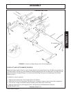
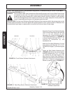
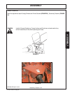
torque. FIGURE 19. Attach the clamp yoke end to the Wing Section Gearboxes by sliding the yoke to the
splined shaft on the Gearbox and tighten the bolts. Move yoke back and forth to make sure yoke is locked
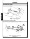
in place. FIGURE 20. Install the Main Driveline with slide collar to the Divider Gearbox by sliding the collar
back while attaching the yoke to the splined shaft on the Divider gearbox. Check to make sure it is locked
in place.
FIGURE 19. Wing Driveline Clutch End Attachment
Figure 20.
Wing Driveline Clamp Yoke End Attachment
NOTE: Divider Gearbox Shield must be
in place to guard connecting yokes and
clutches.
MAIN DRIVELINE
WING DRIVELINE
SLIP CLUTCH END
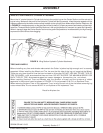
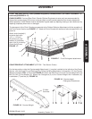
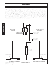
DRIVELINE CLAMP CONE YOKE OPERATING INSTRUCTIONS
Loosen the yoke clamp cone with a 11/16” (17mm) wrench and
remove the cone from yoke. Slide yoke onto the shaft and align
hole for clamping cone with annular groove of gearbox shaft.
Reinstall cone and tighten (75 lb-ft torque). Push and pull the
driveline to ensure it is securely attached to the shaft. Regularly
check the driveline yoke to ensure a tight connection. To remove
the yoke, remove the connecting cone and pull yoke off the shaft.
If the cone cannot be easily removed by hand, drive it out from
the other side using a hammer and punch.
NOTE: The clamping cone is serviced only as a complete
assembly. Do not attempt to disassemble the clamping cone.
Clamping Cone
Driveline Yoke
11/16" Bolt End
R 12-06-01