


MAINTENANCE
MAINTENANCE
SR20M/SR14M 11/01 Maintenance Section 5-11
© 2004 Alamo Group Inc.
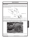
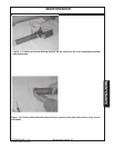
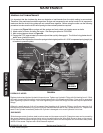
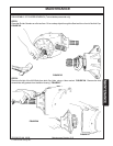
BLADE CARRIER REMOVAL
Remove cotter pin and loosen slotted nut on gear box shaft. Loosen but do not remove the nut until the blade carrier
is loosened. Use a suitable two-jaw gear puller to pull carrier off tapered gear box shaft. If gear puller is not
available use long bar inserted through blade bolt access hole with end against rotor bar. Strike opposite end of bar
with sledge hammer. Rotate blade carrier 180 degrees and repeat process.
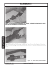
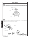
BLADE CARRIER INSTALLATION
Clean the splines on both the blade carrier and output shaft. Position carrier on the gear box output shaft and install
flat washer and 1" hex nut. Tighten nut holding blade carrier to minimum 450 ft. pounds, strike the carrier on the
hub several times with a heavy hammer to seat the hub. Use a suitable spacer over the nut to prevent damage to
the nut and threads. Retighten the nut to 450 ft. pounds. Install and spread cotter pin.
NOTE: After a few hours of operation always recheck blade carrier retaining nut torque.
WARNING Avoid personal injury. Do not work under cutter without support blocks to keep frame
from falling.
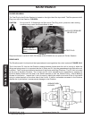
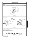
SLIP CLUTCHES
A slip clutch is incorporated on each outboard driveline. The slip clutches are designed to slip, absorb the shock
load, and protect the drivelines of the mower.
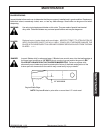
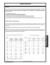
After the first hour of operation, the slip clutches should be checked for overheating. After this first check, inspect
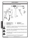
weekly or anytime there is overheating. To adjust the slip clutch, tighten the spring bolts 1/8 (maximum) turn at a
time. See Figure 21 for minimum dimension. DO NOT tighten springs beyond 1-15/32" length (from top of washer
to pressure plate).
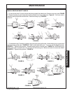
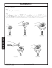
Each slip clutch should be checked periodically and adjusted to compensate for wear. The lining plates are 1/8"
thick when new. Replace after 1/32" wear. If the mower has been idle for an extended period of time, or in wet
weather, before operating check to be sure the friction lining plates are not rusted/frozen together. Should this
occur refer to the procedure described in the "Seasonal Clutch Maintenance" section on the next page.
There are four friction lining plates in the slip clutch. These should be checked weekly for oil or grease, wear, and
moisture which could cause corrosion on the drive plates.
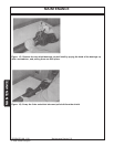
TIRES AND WHEELS
Before working on any tires and wheels make certain the Cutter is jacked up high enough and securely
supported. When installing laminated or airplane tires, be sure the flat side of the lug nut is against the
Wheel.
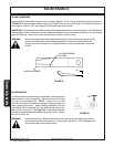
When installing Sectional Tires and Wheels note the direction of travel and the curvature of rubber segments
in the tire (See Assembly Section). Do not exceed 15 M.P.H. on Sectional Tires. When removing Airplane
Tires, let all of the air out of the tire before removing lug nuts or wheel bolts or nuts. Remove valve core to
make certain that there is no air pressure left in tube before separating wheel halves to dismount tires. DO
NOT LOOSEN WHEEL CLAMP BOLTS BEFORE PRESSURE IS REMOVED FROM TUBE AND TIRE TO
PREVENT EXPLOSIVE SEPARATION OF WHEEL HALVES WITH POSSIBLE SERIOUS BODILY INJURY.
Do not exceed 20 M.P.H. on Airplane or Rib Implement Tires.
Maximum airplane tire inflation pressure is 50 PSI, minimum inflation pressure is 20 PSI. Inflate ribbed
implement tires to manufacturer rated PSI as shown on the tire sidewall.