


Assembly Section 3-7
ASSEMBLY
SR20M/SR14M 10/03
ASSEMBLY
© 2004 Alamo Group Inc.
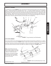
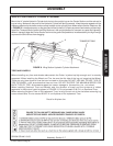
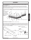
WING SECTION HYDRAULIC CYLINDER ATTACHMENT
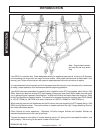
Mount the 14" stroke Hydraulic Cylinder butt clevis to the upright lugs on the Center Section and the rod end to
lugs on wing. Make sure the ports of the Hydraulic Cylinder are facing upwards. Keep the ports capped until the
hoses are attached to the tractor and are ready to attach to the cylinder ports. Make certain that the Restrictor ,(A)
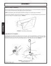
in FIGURE 9, is installed properly on the gland end of the Hydraulic Cylinders to prevent fast lowering of the wings.
Install the Transport Bars to retain the Wing Sections in the upright position for transport on roads and highways.
When in transport keep the Center Section as low to the ground as possible to increase stability but high enough
to prevent the Skid Shoes from dragging.
FIGURE 9. Wing Section Hydraulic Cylinder Attachment.
TRANSPORT BAR
A
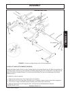
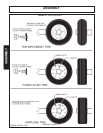
TIRES AND WHEELS
Before installing any tires and wheels make certain the Cutter is jacked up high enough and is securely
supported. When installing the Wheel and Tire, be sure the flat side of the lug nut is against the Wheel.
There are only three types of tires that can be used on this cutter DO NOT USE ANY OTHER TYPE OF
TIRE OR WHEEL, such as automotive tires and rims. DO NOT EXCEED THE MAXIMUM SPEED FOR
EACH TYPE OF TIRE. As excessive speed can cause damage to the machine, tire, and wheel.
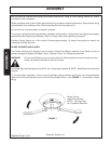
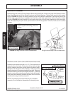
When installing Sectional Tires and Wheels note the direction of travel and the curvature of rubber
segments in the tire and install as shown in FIGURE 10. Do not exceed 15 M.P.H. on Sectional Tires.
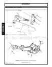
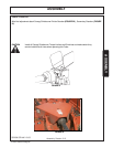
When removing Airplane Tires or Rib Implement Tires, let all of the air out of the tire before removing lug
nuts or wheel bolts. Do not exceed 20 M.P.H. on Airplane or Rib Implement Tires.
Decal for Airplane tire.