


Assembly Section 3-4
SR20M/SR14M 10/03
ASSEMBLY
ASSEMBLY
© 2004 Alamo Group Inc.
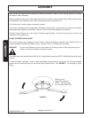
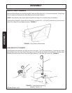
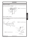
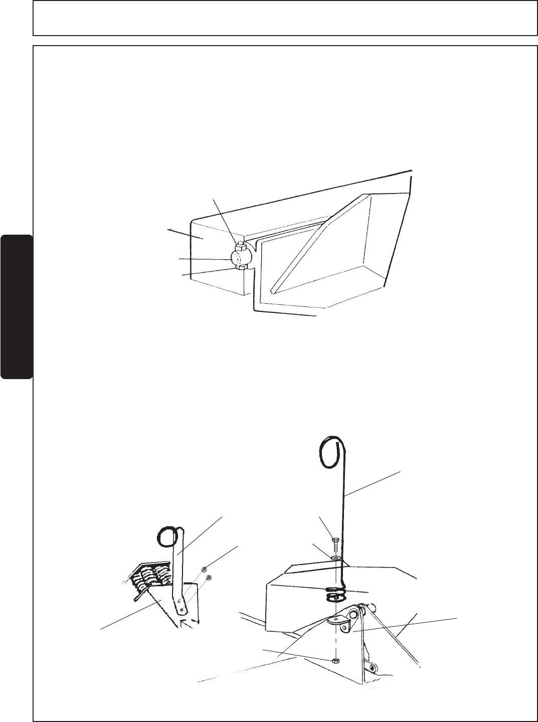
FIGURE 4. Wing Sections Attachments
1
2
3
4
WING SECTIONS ATTACHMENTS
While the Center Section is still solidly blocked, attach the Wing Sections (1) in the horizontal plane. Using Hinge
Pins (2), attach the Right and Left Wing Sections to the Center Sections.
NOTE: Wing Sections may require slight lifting after the Hinge Pin is started to aid pin installation.
Lock the Wing Sections in place with the Hinge Pins. Insert 5/16" x 1-1/2" bolt (3) and locknut (4) at the end of
each of the Hinge Pins and tighten securely. FIGURE 4.
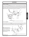
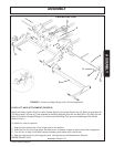
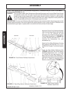
FIGURE 5. Hose Bracket mounting
HOSE BRACKET ATTACHMENT
Hose Brackets are attached in the front and rear of the cutter. The Front Hose Bracket (1) attaches to the Hose
Bracket Mounting on the right side of the tongue mount (2) with Bolt (3), Washer (4) and Nut (5). The Rear Hose
Bracket (6) mounts to the Lower Center Axle Spring Mount (7) with Bolt and Locknut (8) FIGURE 5.
1
2
3
4
5
6
7
8