


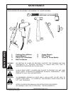

MAINTENANCE
MAINTENANCE
SR20M/SR14M 04/94 Maintenance Section 5-22
© 2004 Alamo Group Inc.
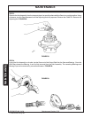
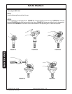
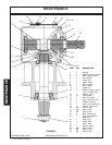
STEP 8
Install a total thickness of .020" of Shims onto Hub Cap. Mount the Hub Caps on the Housing and install four
Bolts, placing them in every other bolt hole, and tighten. Check the rotation of the Gear mesh. The Gear set should
turn smoothly with little noise. The maximum backlash of Gear Mesh should not exceed .022 inches. By adding
Shims to Hub Cap the backlash may be increased, or it may be reduced by removing Shims .
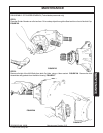
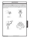
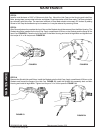
STEP 9
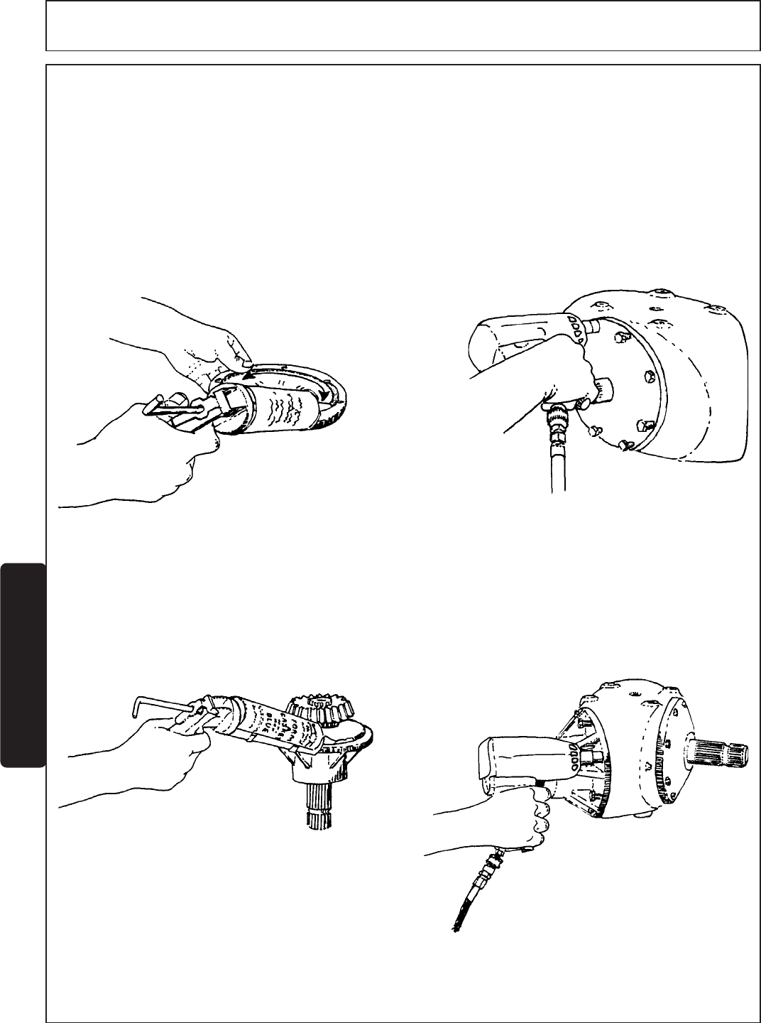
After Gear adjustment is complete the Input Cap and the Gaskets should be removed from the Main Housing. The
Gaskets should be installed on the Input Cap. Apply a small bead of Silicon on the Gaskets and the flange of the
Input Cap. FIGURE 51. Place the Input Cap back on the Main Housing and install all eight Bolts and tighten them
to a torque of 31 to 34 foot pounds. FIGURE 52.
FIGURE 52FIGURE 51
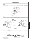
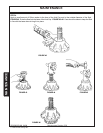
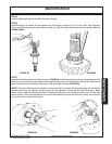
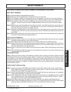
STEP 10
Remove the Spindle Hub and Shims. Install the Gaskets onto the Hub Caps. Apply a small bead of Silicon on the
Gaskets and around the flange of the Hub Cap. FIGURE 53. Install the Spindle Hub assembly back on Main
Housing and install all eight Bolts. Tighten to a torque of 31 to 34 foot pounds. FIGURE 54.
FIGURE 54
FIGURE 53