


MAINTENANCE
SR20M/SR14M 12/96 Maintenance Section 5-25
MAINTENANCE
© 2004 Alamo Group Inc.
RIGHT ANGLE GEARBOX (OUTBOARD) ASSEMBLY & DISASSEMBLY PROCEDURES
INPUT SHAFT REMOVAL
Step 1. Place Gearbox on appropriate work surface.
Step 2. Remove Vent Plug (item #16) or Complete Top Cover (item #18)
Step 3. Turn Gearbox upside doan allowing Oil to drai from gearbox into catch pan for proper disposal.
Step 4. Turn Gearbox right side up and drop bottom into a hole for support or lay it on its side laying flat.
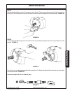
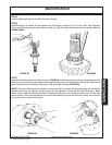
Step 5. Remove Bolts (item # 23) from front Bearing Cap (item # 24), this will allow front cover to be
removed, It may be required to drive a wedge between front cover and main housing to loosen
cover.
Step 6. Remove Input shaft (item #26) and Input Gear (item #27), Input Shaft should pull out with Gear and
Bearing Cones (item #12) still on it, Inner Bearing Cone mat stay in Housing and Outer Bearing
Cone may have came off with front Bearing cover.
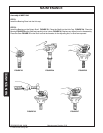
Step 7. Remove Inner Bearing Cone, Inner Spacer (item # 13), Outer Bearing Cone, Input Gear, Check now
for Shims (item # 29,30,31) always note quantity of Shims. Remove outer Spacer (item # 28) from
Input Shaft.
Step 8. Remove Input Seal (item # 25), Bearing Cup (item #12) from front Cover and bearing Cup (item#12)
from back of Main Housing (Casing) (item # 1).
OUTPUT SHAFT REMOVAL
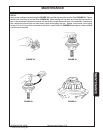
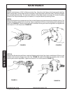
Step 1. Remove Cotter Pin (item # 11) from Nut (item # 10) and Output Shaft (item # 8) this can be done by
reaching through opening in front of Main Housing.
Step 2. Slide Output (Pinion) Geat (item # 9) up off of Output Shaft and out of Main Housing.
Step 3. Output Shaft will come out of Main Housing through the bottom, If Output Seal is still in bottom of
the Main Housing use a Soft Metal (Brass or Aluminum) Pin to Drive Shaft down from the top, This
will drive Output Seal out at the same time.
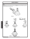
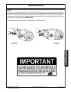
Step 4. Reach in from front or top of Main Housing and remove upper Output Shaft Bearign Cone (item #
12)
Step 5. Frome the Bottom of Main Housing drive out top Bearing Cup (item # 12) and from the top drive out
the bottom Bearing Cup (item # 2).
Step 1. Inspect and Clean all Parts. Check Bearings, Shafts, Gears, Housing and Covers. Shafts should be
inspected at Seal wear areas, Bearing areas, Splines, Threads and all surface areas. Housings for cracks
and condition of all holes that are threaded. Housing and covers where Seals drive in for Burrs and
scratches, If Bearing Cones are replaced always replace Cups with them. Gears should not have and rough
surfaces where the gears run together. On Main Housing remove any old Gasket Sealer, Scratches, Wash
and completely clean it.
PARTS INSPECTION
OUTPUT SHAFT INSTALLATION
Step 1. Install Upper Output Shaft Bearing Cup (item # 12) into Main Housing from the top, Install Output
Shaft Lower Bearing Cup (item # 2) into Main Housing (item # 1) from the bottom, Make sure both
Bearing Cup are seated firmly against housing.
Step 2. Install Lower Bearing Cone (item #2) down over Output Shaft from top making sure it is completely
seated against shoulder on lower part of Output Shaft.
Step 3. Insert Output Shaft (item # 8) into Main Housing from the bottom till Lower Bearing Cone is seated
into Lower Bearing Cup, Slide Upper Bearing Cone down over Output Shaft from the till it seats
down against and into upper output Shaft Bearing Cup.
Step 4. Slide Output Gear (item # 9) down over Output Shaft till it sits against upper Bearing Cone.
Step 5. Install Output Shaft Bearing Adjusting nut (item # 10) Tighten Nut to set Pre-Load on Output Shaft
Bearings. Bearing Preload should be from 12 to 14 inch pounds of Rolling Torque.