


Assembly Section 3-6
SR20M/SR14M 10/03
ASSEMBLY
ASSEMBLY
© 2004 Alamo Group Inc.
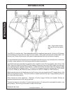
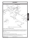
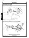
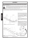
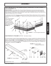
AXLE ADJUSTMENT ROD ATTACHMENT
Attach the Axle Adjustment Rod w/Bushings (1) to the Center Axle (2) and Wing Axle (3) with bolts and locknuts
(4). Install Spacers (5) as shown. FIGURE 7.
FIGURE 7. Axle Adjustment Rod Attachment
NOTE: Wing in upright position
3
4
4
2
1
5
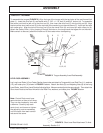
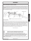
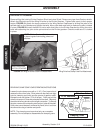
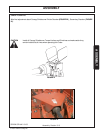
CENTER AXLE HYDRAULIC CYLINDER ATTACHMENT
Install the clevis rod end (1) of the 8" stroke Hydraulic Cylinder to the lug on the Center Axle (2). The clevis base
fastens between the flats on Spring Assembly (3) on the Center Section. FIGURE 8.
FIGURE 8. Center Axle Hydraulic Cylinder Attachment
1
2
3