


Assembly Section 3-2
SR20M/SR14M 10/03
ASSEMBLY
ASSEMBLY
© 2004 Alamo Group Inc.
Set up cutter as received from factory with these instructions. Refer to Parts Listing Section for further
information when necessary.
Select a suitable working area. Open parts box and lay out parts to make location easy. Refer to parts listing
and exploded view drawings in the Parts Listing Section and the packing list.
Cut all wire ties, including those on blades if present.
This cutter is shipped partially assembled. Assembly will be easier if components are aligned and loosely
assembled before tightening hardware. Refer to Torque Chart when tightening hardware.
Position Center Section on a flat surface. Elevate approximately 10 inches from ground to permit the
installation of Wing Sections.
BLADE CARRIER AND BLADES
The Frame sections are shipped from the factory without the Blades attached to the Blade Carrier to
prevent damage to Blades and Blade Carrier. Optional Flat or Fan Blades are available.
WARNING Do not install Blades or do any work under the Cutter sections unless the section(s) are
safely and securely blocked or latched in place.
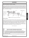
The Blade Bolts must be tightened to 350 ft. lbs. torque before operating. NOTE: Blade Bolts have left-hand
threads.
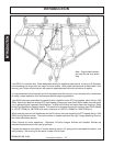
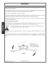
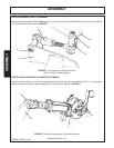
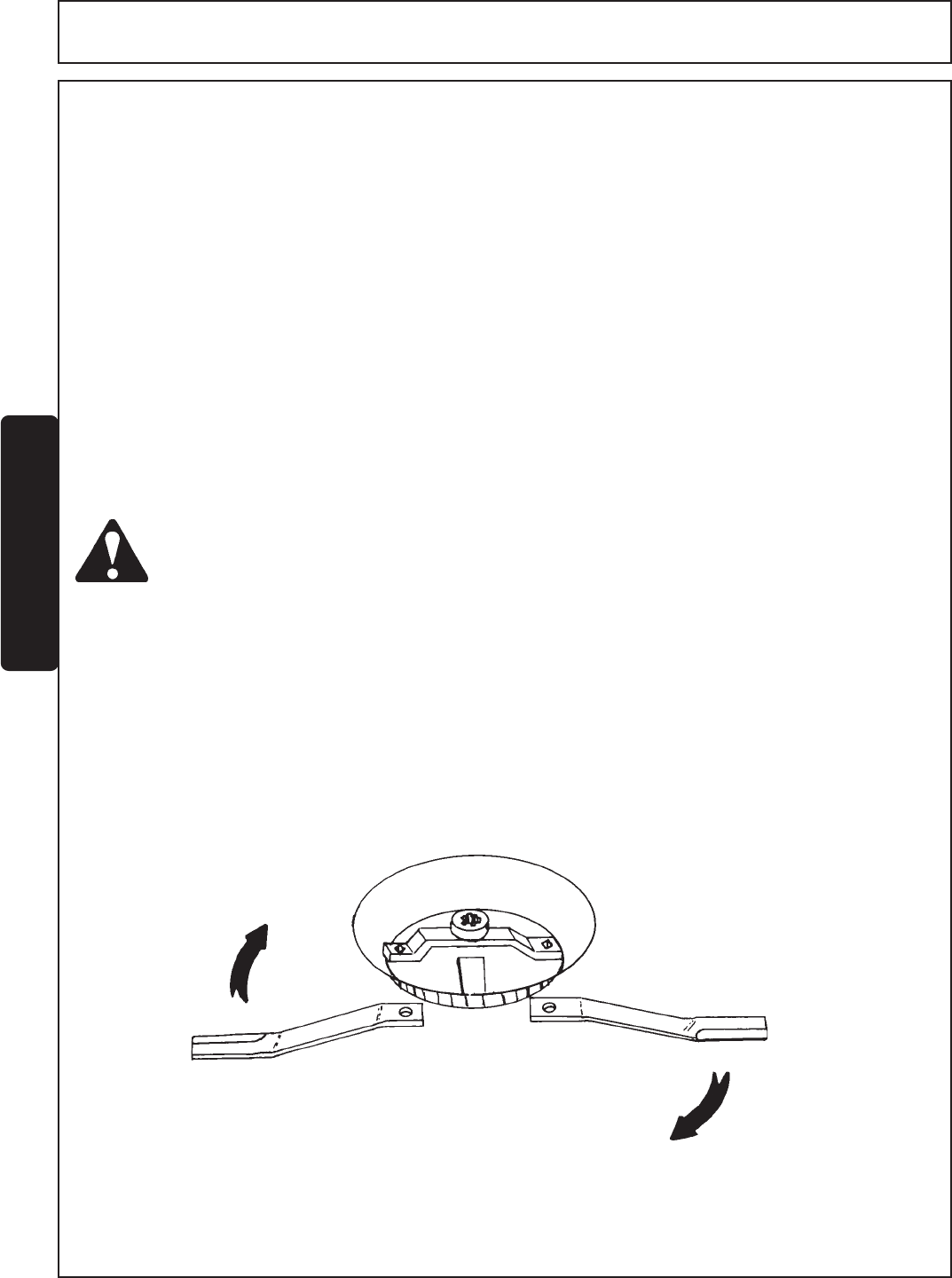
To insure proper installation, check to see that Blade cutting surfaces are correct for counterclockwise
rotation on the Center Section and on the Left Wing Blade Carrier. See FIGURE 1. (Clockwise on Right
Wing)
FIGURE 1
Blade Carrier
Right Wing Shown
NOTE: Cutting Edge
for Clockwise Rotation