ASSEMBLY
INTERSTATER 02/11 Assembly Section 3-26
© 2011 Alamo Group Inc.
ASSEMBLY
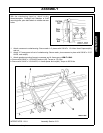
1. Properly mount rear mower to tractor and install
driveline. See INSTALLATION AND
DRIVELINE SECTIONS.
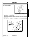
2. Attach PTO shield to mounting bracket. Snap-
on shield is positioned so lower ears engage
holes in bracket; upper ears rest on top of
bracket. Bolt-on shield is secured with 3/8 NC x
3/4 HHCS (4 places).
3. Attach belt guard to cutter housing then
reattach belt guard fender.
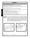
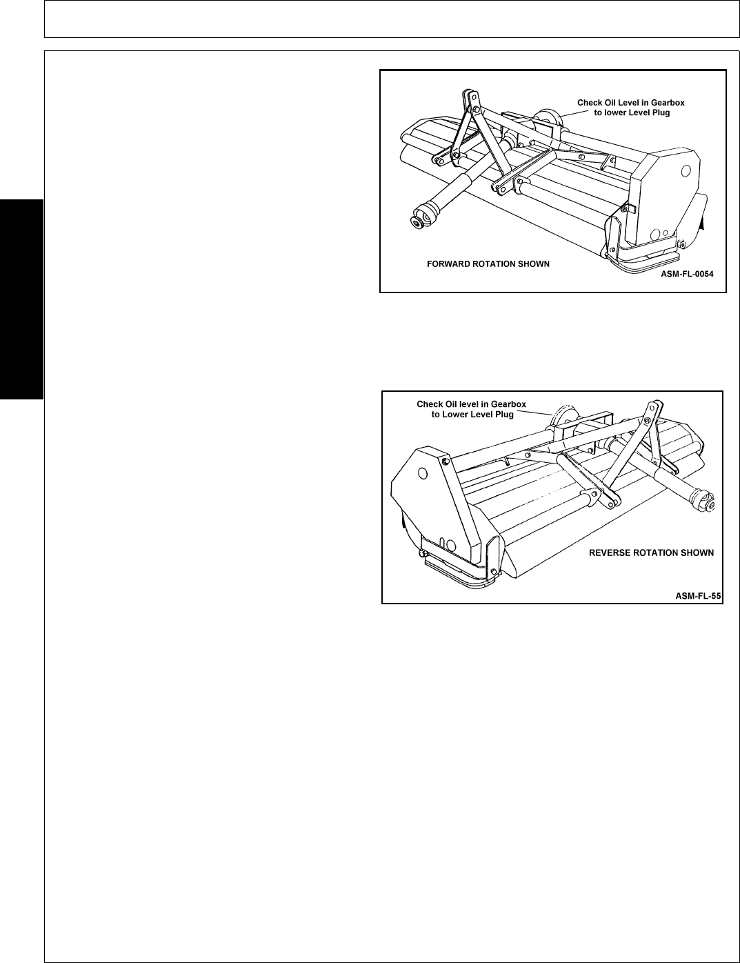
Belt Guard, FORWARD ROTATION
Three 1/2 NF x 1-1/4 HHCS and nuts.
Belt Guard, REVERSE ROTATION
One 1/2 NF x 1 HHCS (upper attaching pollinator
1/2NF x 1-1/4 HHCS two plain washers, and one
nut. Plain washers are located at upper two belt
guard attaching points
.
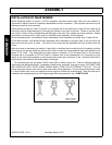
UNIVERSAL SLIP JOINT (PTO SHAFT): Refer to
instructions supplied with shaft.
To install the driveline separates slip joint halves,
then install them onto mower gearbox input shaft
and tractor PTO driveline according to illustration on
PTO shaft shield. Hold halves side by side, then
raise and lower the mower to determine that there
is no interference between halves when in the
shortest position, and that there is a specified
minimum amount of overlap (see PTO SHAFT -
PARTS LIST section) when in the longest position.
Once it is determined that the shaft will cause no
clearance problems, remove the halves, rejoin them
and install the assembled PTO shaft between the
tractor and the mower.
After attaching PTO shaft, slowly raise and lower
mower to make sure shaft will not make any contact
with “A-Frame” or mower head. If a problem exists,
change mounting position or lengths of lift chains by
removing or adding links.


