ASSEMBLY
INTERSTATER 02/11 Assembly Section 3-11
© 2011 Alamo Group Inc.
ASSEMBLY
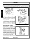
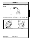
CONTROL VALVE
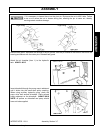
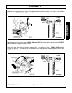
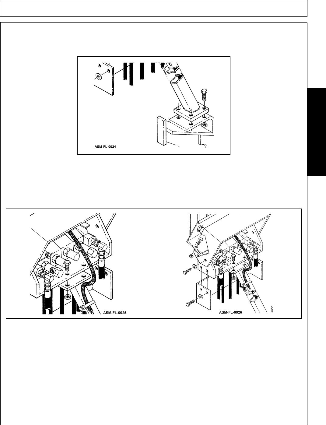
Attach valve stand to the top of the right lift cylinder support with (3) 1/2” x 1-1/2” bolts, and (3) 1/2” locknuts.
ASM-FL-0024
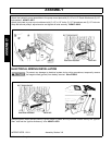
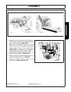
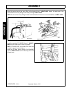
Attach valve stand to the valve mount bracket with (2) 3/8”x1-1/4” bolts and (2) 3/8” locknuts. ASM-FL-0025
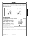
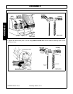
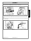
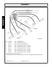
Attach control valve to the valve stand with (2) 3/8”x1” bolts, (2) 3/8” locknuts. Attach the top cover and the
bottom cover to the valve mount bracket with (8) 3/8”x1” bolts, (8) 3/8” washers and (8) locknuts. ASM-FL-
0026
.


