


ASSEMBLY
INTERSTATER 02/11 Assembly Section 3-22
© 2011 Alamo Group Inc.
ASSEMBLY
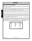
INSTALLATION OF REAR MOWER
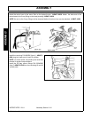
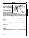
Before attaching mower to tractor, it will be necessary that each tractor lower hitch arm has freedom of
movement so that the mover is completely independent of tractor movement. This will allow the mower to pivot
sideways as well as move vertically.
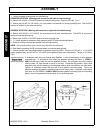
Some tractors provide this “float” by means of an optional slot in the lower end of each lift link, others by lift
links which can be made telescopic by changing the position of the pins in the links. Failure to provide “float”
may result in failure of the cutterhousing and bearings in the roller, thus voiding the mover warranty. Should
your tractor not have a built in “float” option, a flexible lift chain assembly will be required.
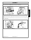
On all centered mowers, two flexible lift chain assemblies will be necessary to provide “float” to each lift link.
On all offset mowers, one flexible lift chain assembly will be necessary to provide “float” to the lift link on the
same side that the mover is offset. The other lift link should be the adjustable stiff link furnished with the
tractor.
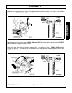
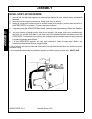
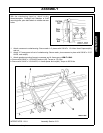
After the mower is attached to the tractor’s 3-point hitch, but before the universal slip joint is installed, and with
the mover on the ground, adjust the top link of the hitch to make the mower gearbox input shaft parallel to the
tractor P.T.O. shaft. This relationship provides optimum operation of the universal joints in the driveline.
Driveline that is not parallel to PTO will result in vibration due to the characteristic of a universal joint that
results in the output end speeding up and slowing down twice each revolution of the universal jointed shaft.
Adjust the top link whenever the cutting height is changed.
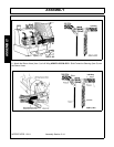
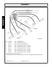
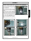
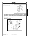
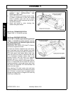
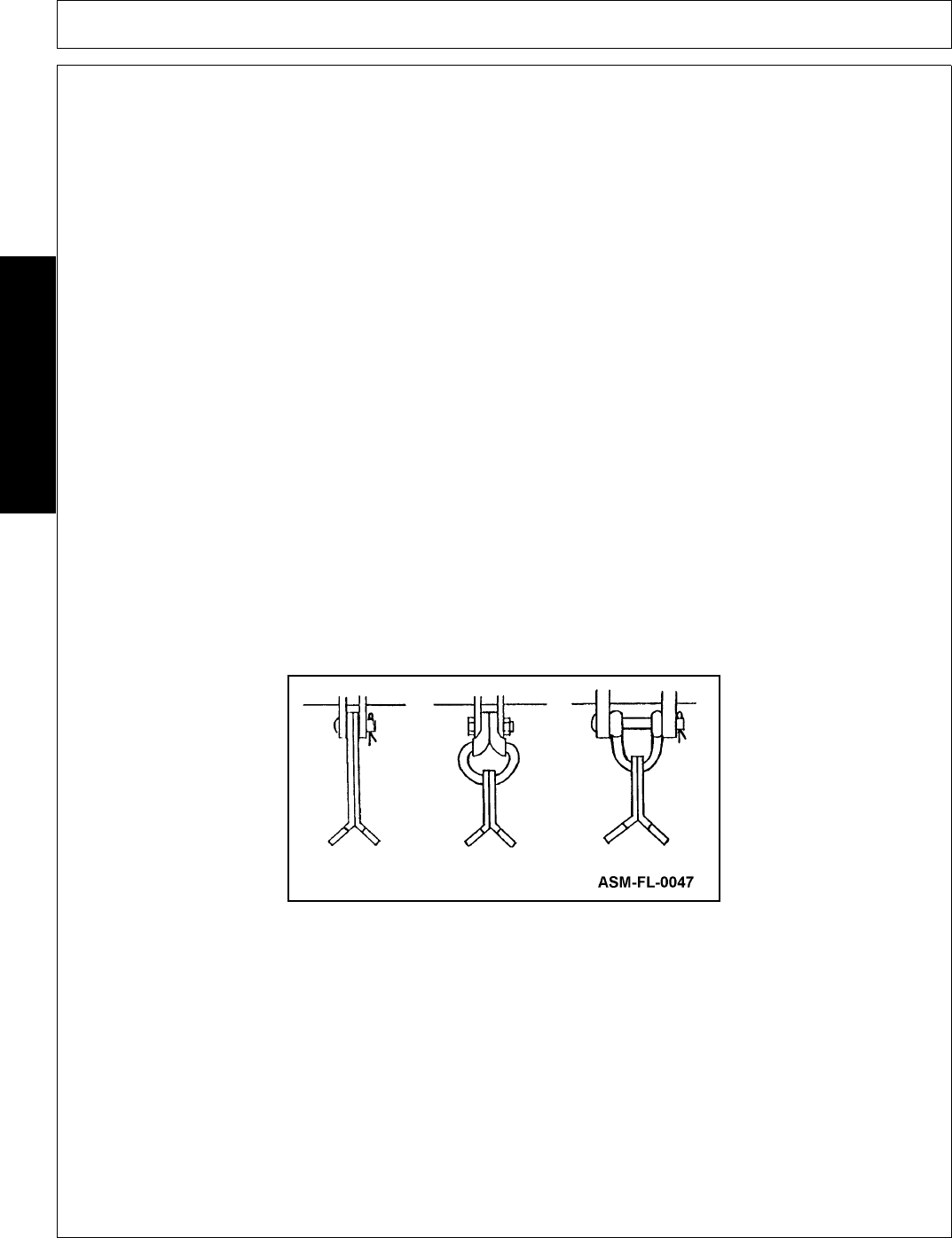
1. Tip cutterhousing back and place a block under roller to safely support unit. Remove shipping skids and
drive pulley side belt guard fender. If necessary, install knives, as shown, one row at a time. ALL KNIFE PINS
ARE INSTALLED WITH THEIR HEADS FACING AWAY FROM THE CUTTERSHAFT PULLEY. This will
locate cotter pins where knives cannot reach them when flexing backward. The housing side sheet has a hole
in it which allows knife pins to be inserted into end lugs from outside the cutterhousing. After the cotter pin is
installed, bend extended prong at a 45 Degree angle with prong parallel to lug. ASMP-FL-0047