


ASSEMBLY
INTERSTATER 02/11 Assembly Section 3-5
© 2011 Alamo Group Inc.
ASSEMBLY
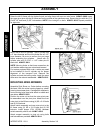
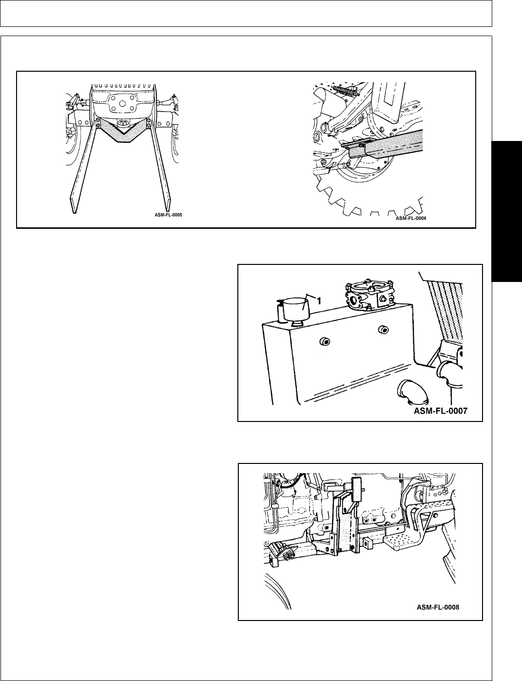
5. Lift the rear of the frame and secure with (4) 1/2" x 1 1/2" & (2) 5/8" x 1/3/4" bolts. Install the remaining front
hardware. ASM-FL-0006
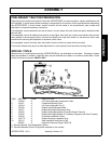
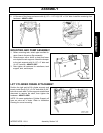
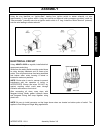
MOUNTING AND PUMP ASSEMBLY
1. Before mounting tank, attach pipe manifold for
return lines to the return filter assembly.
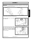
2. Raise bumper with a forklift or hoist and lower
onto hydraulic tank supports. Attach the bumper
to the tank supports with (4) 1/2” x 2" bolts and
(4) 1/2" locknuts. ASM-FL-0007
3. Now tighten all hardware for mainframe, tank
support, tank, and bumper.
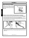
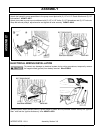
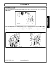
LIFT CYLINDER FRAME ATTACHMENT
Position the right and left lift cylinder supports and
loosely install the (6) 3/4" x 2-1/4" bolts and (6) 3/4"
locknuts to each side. Pull the supports outward and
downward to remove the slack, then tighten the
hardware. ASM-FL-0008
NOTE: On some applications Cylinder Support will
have an extra set of holes. Refer to Installation
Drawing for correct mounting.