


ASSEMBLY
INTERSTATER 02/11 Assembly Section 3-4
© 2011 Alamo Group Inc.
ASSEMBLY
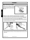
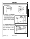
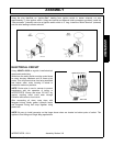
DRIVE COUPLING ATTACHMENT
Assemble the front coupling to the engine
crankshaft pulley using the hardware supplied with
the coupling. Due to the variations in the tractor
models, it may be necessary to remove some of the
sheet metal to facilitate mounting of the coupling.
ASM-FL-0002.
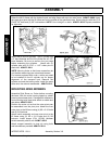
HYDRAULIC TANK, SUPPORTS AND MAINFRAME ATTACHMENT
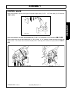
1. Attach the left hydraulic tank support and step weldment to the tractor with (4) bolts provided in your Mount
Kit. Refer to your particular Tractor Installation Drawing for part numbers and quantities. ASM-FL-0003
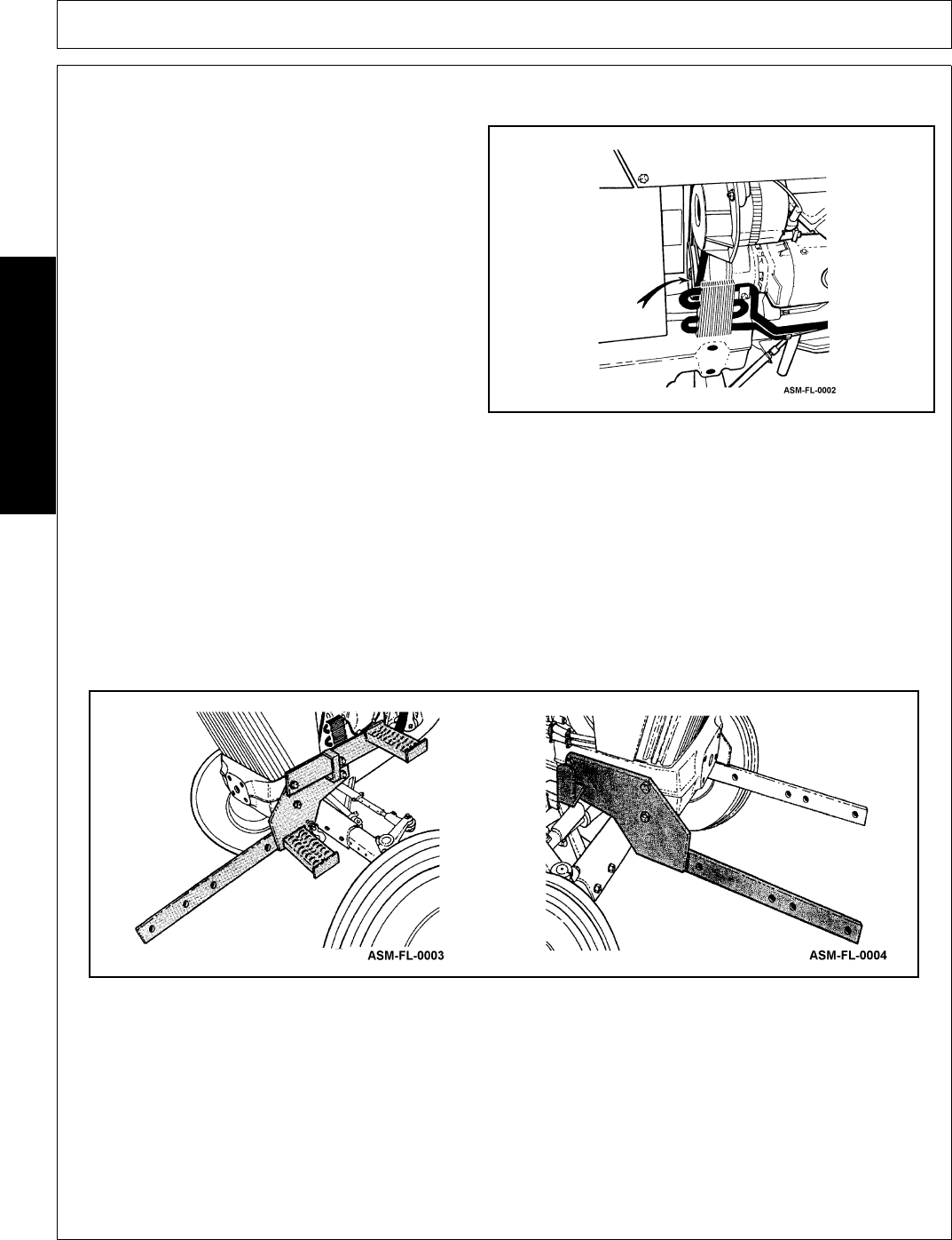
2. Attach the right hydraulic tank support to the tractor with (4) bolts provided in your Mount Kit. Refer to your
particular Tractor Installation Drawing for part numbers and quantities. ASM-FL-0004
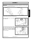
3. To make assembly easier, the hard plumbing assembly should be installed on the Mainframe before the
Mainframe is installed. Use (2) 1/2” x 1-1/2” bolts, (2) 1/2" Flatwashers, and (2) 1/2" Locknuts. Metal tubing
on assembly will need to be loosened to install bolts.
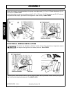
4. Position the mainframe under the tractor. Lift the front of the frame and install the top two 5/8” x 2" bolts.
Install a 5/8" flatwasher and a 5/8" locknut on the bolts and tighten enough to hold the frame in place.
ASM-FL-0005