


30 Chapter 1
Signal Generator Overview
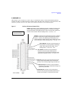
Rear Panel
33. EXT 2
This female BNC input connector (functional only with Options UNT, UNU, or UNW) accepts a ±1V
p
signal for AM, FM, and ΦM. With AM, FM, or ΦM, ±1V
p
produces the indicated deviation or depth.
When ac-coupled inputs are selected for AM, FM, or ΦM and the peak input voltage differs from 1 V
p
by more than 3 percent, the HI/LO annunciators light on the display. The input impedance is
selectable as either 50 or 600 ohms and damage levels are 5 V
rms
and 10 V
p
. On signal generators
without Option 1EM, this connector is located on the front panel.
34. PULSE SYNC OUT
This female BNC output connector (functional only with Options UNU or UNW) outputs a
synchronizing TTL-compatible pulse signal that is nominally 50 ns wide during internal and triggered
pulse modulation. The nominal source impedance is 50 ohms. On signal generators without Option
1EM, this connector is located on the front panel.
35. PULSE VIDEO OUT
This female BNC output connector (functional only with Options UNU or UNW) outputs a TTL-level
compatible pulse signal that follows the output envelope in all pulse modes. The nominal source
impedance is 50 ohms. On signal generators without Option 1EM, this connector is located on the
front rear panel.
36. PULSE/TRIG GATE INPUT
This female BNC input connector (functional only with Options UNU or UNW) accepts an externally
supplied pulse signal for use as a pulse or trigger input. With pulse modulation, +1 V is on and 0 V
is off (trigger threshold of 0.5 V with a hysteresis of 10 percent; so 0.6 V would be on and 0.4 V
would be off). The damage levels are ±5V
rms
and 10 V
p
. The nominal input impedance is 50 ohms.
On signal generators without Option 1EM, this connector is located on the front panel.
37. ALC INPUT
This female BNC input connector is used for negative external detector leveling. This connector
accepts an input of −0.2 mV to −0.5 V. The nominal input impedance is 120 kohms and the damage
level is ±15 V. On signal generators without Option 1EM, this connector is located on the front panel.
38. DATA CLOCK
This female BNC input connector (E8267D only) is CMOS compatible and accepts an externally
supplied data clock input signal to synchronize serial data for use with the internal baseband
generator (Option 601/602). The expected input is a 3.3 V CMOS bit clock signal (which is also TTL
compatible) where the rising edge is aligned with the beginning data bit. The falling edge is used to
clock the DATA and SYMBOL SYNC signals. The maximum clock rate is 50 MHz. The damage levels
are > +5.5 V and < −0.5V. The nominal input impedance is not defined. On signal generators without
Option 1EM, this connector located on the front panel.