


Chapter 7 177
Custom Real Time I/Q Baseband
Working with Phase Polarity
Working with Phase Polarity
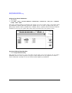
To Set Phase Polarity to Normal or Inverted
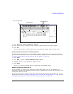
1. Press Mode > Custom > Real Time I/Q Baseband > More (1 of 3) > Phase Polarity Normal Invert.
Phase Polarity Normal Invert enables you to either leave the selection as Normal (so that the
phase relationship between the I and Q signals is not altered by the phase polarity function), or
set to Invert and invert the internal Q signal, reversing the rotation direction of the phase
modulation vector.
When you choose Invert, the in-phase component lags the quadrature-phase component by 90° in
the resulting modulation. Inverted phase polarity is required by some radio standards and it is
useful for lower sideband mixing applications. The inverted selection also applies to the I, I-bar,
Q, and Q-bar output signals.
Working with Differential Data Encoding
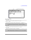
The Diff Data Encode Off On menu enables you to toggle the operational state of the signal
generator’s differential data encoding.
• When set to Off, data bits are not encoded prior to modulation.
• When set to On, data bits are encoded prior to modulation. Differential encoding uses an
exclusive-OR function to generate a modulated bit. Modulated bits will have a value of 1 if a data
bit is different from the previous bit or they will have a value of 0 if a data bit is the same as
the previous bit.
This section provides information about the following:
• Understanding Differential Encoding
• “Using Differential Encoding” on page 181
Understanding Differential Encoding
Differential encoding is a digital-encoding technique whereby a binary value is denoted by a signal
change rather than a particular signal state. Using differential encoding, binary data in any
user-defined I/Q or FSK modulation can be encoded during the modulation process via symbol table
offsets defined in the Differential State Map.
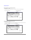
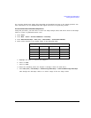
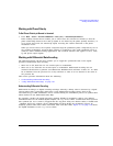
For example, consider the signal generator’s default 4QAM I/Q modulation. With a user-defined
modulation based on the default 4QAM template, the I/Q Values editor contains data that represent
four symbols (00, 01, 10, and 11) mapped into the I/Q plane using two distinct values, 1.000000 and
-1.000000. These four symbols can be differentially encoded during the modulation process by
assigning symbol table offset values associated with each data value. Figure 7-3 on page 178 shows
the 4QAM modulation in the I/Q Values editor.