


10 Chapter 1
Signal Generator Overview
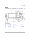
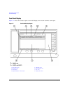
Front Panel
12. EXT 2 INPUT
This female BNC input connector (functional only with Options UNT, UNU, or UNW) accepts a ±1V
p
signal for AM, FM, and ΦM. With AM, FM, or ΦM, ±1V
p
produces the indicated deviation or depth.
When ac-coupled inputs are selected for AM, FM, or ΦM and the peak input voltage differs from 1 V
p
by more than 3 percent, the HI/LO annunciators light on the display. The input impedance is
selectable as either 50 or 600 ohms and damage levels are 5 V
rms
and 10 V
p
. On signal generators
with Option 1EM, this connector is located on the rear panel.
13. LF OUTPUT
This female BNC output connector (functional only with Option UNT) outputs modulation signals
generated by the low frequency (LF) source function generator. This output is capable of driving
3V
p
(nominal) into a 50 ohm load. On signal generators with Option 1EM, this connector is located
on the rear panel.
14. Mod On/Off
This hardkey (E8267D and E8257D with Options UNT, UNU, or UNW and E8267D only) enables or
disables all active modulation formats (AM, FM, ΦM, Pulse, or I/Q) applied to the output carrier
signal available through the RF OUTPUT connector. This hardkey does not set up or activate an AM,
FM, ΦM, Pulse, or I/Q format; each modulation format must still be set up and activated (for
example,
AM > AM On) or nothing is applied to the output carrier signal when the Mod On/Off hardkey
is enabled. The MOD ON/OFF annunciator indicates whether active modulation formats have been
enabled or disabled with the
Mod On/Off hardkey.
15. ALC INPUT
This female BNC input connector is used for negative external detector leveling. This connector
accepts an input of −0.2 mV to −0.5 V. The nominal input impedance is 120 kohms and the damage
level is ±15 V. On signal generators with Option 1EM, this connector is located on the rear panel.
16. RF On/Off
Pressing this hardkey toggles the operating state of the RF signal present at the RF OUTPUT
connector. Although you can set up and enable various frequency, power, and modulation states, the
RF and microwave output signal is not present at the RF OUTPUT connector until
RF On/Off is set to
On. The
RF On/Off annunciator is always visible in the display to indicate whether the RF is turned
on or off.
17. Numeric Keypad
The numeric keypad consists of the 0 through 9 hardkeys, a decimal point hardkey, and a backspace
hardkey ( ). The backspace hardkey enables you to backspace or alternate between a positive
and a negative value. When specifying a negative numeric value, the negative sign must be entered
prior to entering the numeric value.