


Chapter 11 225
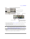
Peripheral Devices
N5102A Digital Signal Interface Module
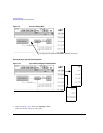
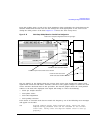
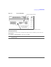
From this softkey menu, set all of the clock parameters that synchronize the clocks between the
N5102A module and the PSG. You can also change the clock signal phase so the clock occurs
during the valid portion of the data. Figure 11-14 shows the clock setup menu.
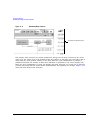
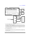
Figure 11-14 Clock Setup Softkey Menu for a Parallel Port Configuration
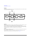
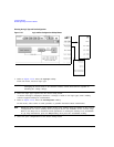
The top graphic on the display shows the current clock source that provides the output clock
signal at the Clock Out and Device Interface connectors. The graphic changes to reflect the clock
source selection discussed later in this procedure. The bottom graphic shows the clock position
relative to the data. The displayed clock signal will change to reflect the following:
• clocks per sample selection
• clock phase choice
•clock skew adjustment
• clock polarity selection
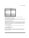
If the device or external clock does not match the frequency, one of the following error messages
will appear on the PSG:
805 Digital module output FIFO overflow error; There are more
samples being produced than can be consumed at the current
clock rate. Verify that the digital module clock is set up
properly.
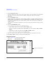
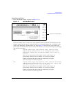
Inactive for a serial port configuration and the IF signal type
Active for only the Internal clock source selection
Inactive for clock rates below 25 MHz
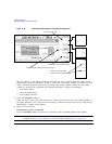
Inactive for clock rates below
10 MHz and above 200 MHz