


226 Chapter 11
Peripheral Devices
N5102A Digital Signal Interface Module
This error is reported when the output FIFO is overflowing in the
digital module. This error can be generated if an external clock
or its reference is not set up properly, or if the internal VCO is
unlocked.
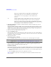
806 Digital module output FIFO underflow error; There are not
enough samples being produced for the current clock rate.
Verify that the digital module clock is set up properly.
This error is reported when the output FIFO is underflowing in the digital
module. This error can be generated if an external clock or its reference is not
set up properly, or if the internal VCO is unlocked.
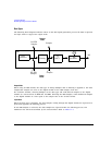
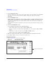
2. If the port configuration is parallel or parallel interleaved, using an IQ signal type, press the
Clocks Per Sample softkey.
Notice that multiple clocks per sample can be selected. Some DACs require the ability to clock
multiple times for each sample; having a clocks per sample value greater than one reduces the
sample rate by a factor equal to the selected number of clocks per sample. The sample rate is
viewed on the first-level and Data Setup softkey menus.
3. Select the clocks per sample value to fit the test.
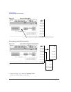
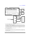
4. Press the
Clock Source softkey.
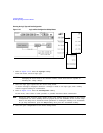
From this menu, select the clock signal source. With each selection, the clock routing display in
the signal generator clock setup menu will change to reflect the current clock source. This will be
indicated by a change in the graphic.
5. Select the clock source.
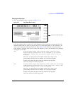
If External or Device is Selected
Press the
Clock Rate softkey and enter the clock rate of the externally applied clock signal.
NOTE The clock phase and clock skew may need to be adjusted each time the clock rate setting is
changed. Refer to “Clock Timing for Phase and Skew Adjustments” on page 215.
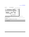
For the External selection, the signal is supplied by an external clock source and applied to the Ext
Clock In connector. For the
Device selection, the clock signal is supplied through the Device
Interface connector, generally by the device under test.
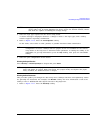
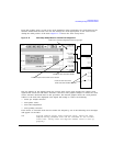
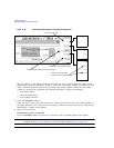
If Internal is Selected
Using an external frequency reference, the N5102A module generates its own internal clock signal.
The reference frequency signal must be applied to the Freq Ref connector on the digital module.
a. Press the
Reference Frequency softkey and enter the frequency of the externally applied frequency
reference.
b. Press the
Clock Rate softkey and enter the appropriate clock rate.
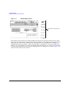
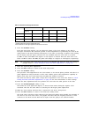
Table 11-8 provides a quick view of the settings and connections associated with each clock
source selection.