


32
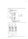
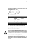
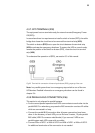
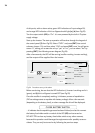
Physical structure of the RS232.
• Pin-out
- Pin 2. RXD. Serial data reception.
- Pin 3. TXD. Serial data transmission.
- Pin 5. GND. Signal mass.
• Communication protocol of the RS232.
The communication protocol used is of “MASTER/SLAVE” type.
The computer or computer system (“MASTER”) asks about a certain data,
and the UPS (“SLAVE”) answers immediately with the required data. Firstly it
will be programmed the communication channel of the computer with the
same parameters as the communication channel of the UPS. Then we will be
prepared to start the communication and therefore send the UPS the first
question. If we have any problem in the middle of the communication, it will
be advisable to repeat the channel initialization sequence.
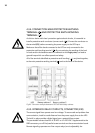
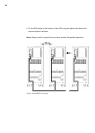
Physical structure of the RS485.
Unlike other serial communication links, this uses only 2 wires (pins 4 and 9 of the
female DB9 connector) to perform the dialogue between the systems connected
to the network. The communication will be established by sending and receiving
signals in differential mode, which gives the system great immunity to noise and
a long reach (approx. 800 m).
• Pin-out
- Pin 4. Output signal A (+)
- Pin 9. Output signal B (–)
• Communication protocol
The communication protocol of the RS485 channel is developed to enable
the UPS to communicate with other computer systems that use the same bus.
The communication parameters RS232 and RS485 are the following:
• Communication speed: 1200, 2400, 4800, 9600 or 19200 Baud.
• No. information bits: 8 Bits.
• No. stop bits: 1 or 2 stop bits.
• Parity bit: - Even, Odd