


30
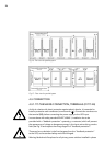
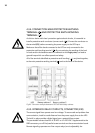
4.3.4. CONNECTION MAIN PROTECTIVE EARTHING
TERMINAL ( ) AND PROTECTIVE EARTH BONDING
TERMINAL ( )
As this is a device with class I protection against electric shocks, it is essential to
install a protective earth conductor (connect earth ( )). Connect the conductor to
the terminal (X5), before connecting the power supply to the UPS input.
Make sure that all the loads connected to the UPS are only connected to the
protective earth bonding terminal
( )
. By not restricting the earthing of the load
or loads and/or the batteries case/s or cabinet/s to this single point,
can lead to
ground loops which can affect operational safety.
All of the terminals identified as protective earth bonding
( )
, are joined together,
to the main protective earthing terminal
( ) and to the frame of the device.
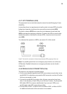
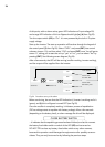
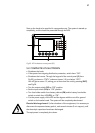
4.3.5. INTERFACE RELAY CONTACTS, CONNECTOR (X32)
The remote signal lines operate over low voltage. To ensure safe and problem free
communication, install at a safe distance from the power supply lines to the UPS.
The built in relays provide a digital signal over a potential free contact.
The permissible contact load is 6 A 30 VDC or 6 A 100 VAC. Supplemental to the
DB9 connector you will find parallel screw terminals on the communication board.
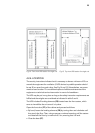
Remote signaling operates over fiver output relays (one is adjustable), the
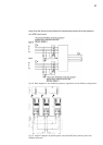
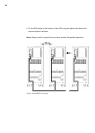
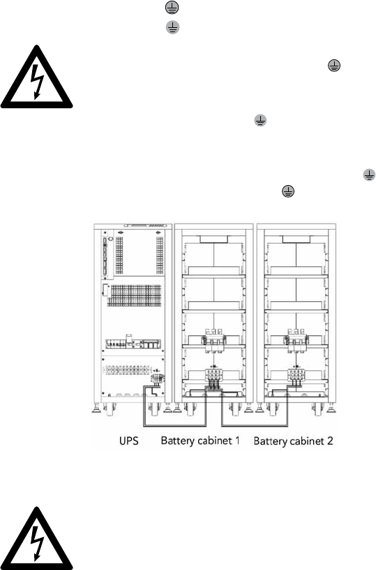
Fig.20: Connection example between a UPS and two battery cabinets