


13
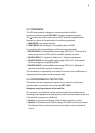
3.1.2
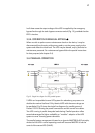
CORRESPONDING LEGENDS FOR THE EQUIPMENT VIEWS
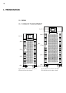
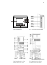
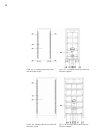
Protection and handling elements (Q):
(Q1a) Input circuit breaker or switch according to power of the equipment
(Q2) Output switch
(Q3) Battery fuse holder switch with 3 fuses (models up to 40 kVA) or switch
(for higher models)
(Q4) Not available for Protect 2.33 2.0
(Q5) Maintenance bypass switch
(Q8) Battery fuse holder switch 3 fuses, located in the battery cabinet
Connecting elements (X):
(X1) Phase input terminal R
(X2) Phase input terminal S
(X3) Phase input terminal T
(X4) Neutral input terminal N
(X5) Main protection earthing terminal (
)
(X6) Phase output terminal U
(X7) Phase output terminal V
(X8) Phase output terminal W
(X9) Neutral output terminal N
(X10) Earth bonding terminal for load or loads and/or battery cabinet ( )
(X11) Battery terminal +
(X12) Battery terminal –
(X23) Battery terminal N
(X31) DB9 connector COM RS232- and RS485 ports
(X32) DB9 connector relay interface
(X36) Connector for connecting cable for parallel use
(X47) Battery terminal + of external batteries cabinet
(X48) Battery terminal – of external batteries cabinet
(X49) Battery terminal N (middle tap) of external batteries cabinet
(X50) Terminals for external EPO