


17
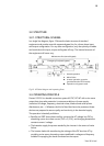
In all these cases the output voltage of the UPS is supplied by the emergency
bypass line through the static bypass commuter switch (Fig. 12), provided that the
EPO is inactive.
3.3.4. OPERATION IN MANUAL BYPASS
When we wish to perform some maintenance check on the device, it may be
disconnected from the mains without any need to cut the power supply to the
system and affect the critical load. The UPS may be altered, only by technical or
maintenance personnel. For maintenance bypass follow the special instructions
for that purpose (refer chapter 5.4).
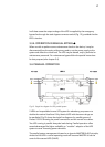
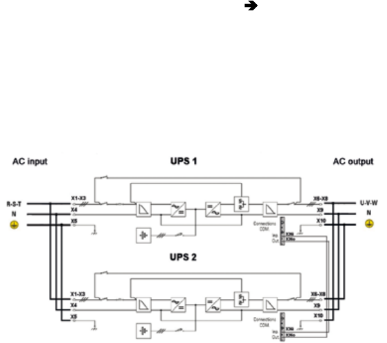
3.4. PARALLEL OPERATION
2 UPS’s can be paralleled to one UPS system for redundancy purposes or to
double the maximal load level. Only identical UPS with the same ratings can
be paralleled. Fig.13 shows the single line diagram of a parallel system of
Protect 2.33 2.0 showing the power connections and the control bus cables.
Two UPS running in parallel always do load-sharing. Parallel operation offers
several advantages like higher availability or “modular” adaption of the UPS
system to cover increasing power demands.
The parallel system management is based on a dynamic MASTER-SLAVE principle,
where the first UPS in normal operating mode will become MASTER. It has the
control of the second UPS (SLAVE).
Fig.13: Single line diagram for UPS parallel system