


22
The cross sections of all of the connecting cables must in each case be sized
according the fuse selected.
In cases were added input, output or bypass peripherals to the UPS (e.g.
transformers or autotransformers) currents are stated in the nameplates of the
peripherals and must to be taken into account in order to use suitable cross
sections. Always respect the local and/or national low voltage electro-technical
regulations.
If isolation transformers are present in the installation at the input and/or output
of the UPS, they have to be fitted in with protection against indirect contacts
(earth leakage breaker) at the output of each transformer. Electrically insulated
of the transformer will impede the tripping of protection installed at the primary
winding of the transformer in cases were an short circuit in the secondary winding
(output of isolation transformer) may occur.
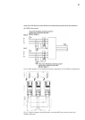
Note that all neutral terminals for input, output and battery are connected inside
the UPS.
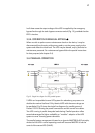
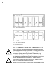
The cable routing or housing passages supplied fitted to the metal structure are
those recommended to correctly fix the input, output and bypass wires with the
sections determined by the national low voltage electro-technical regulations in
accordance with the currents of the device.
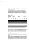
PROTECT 2.33 2.0
Equipment
power
(kVA)
3 x 380 V 3 x 400 V 3 x 415 V
Input
Output
Bypass
Input
Output
Bypass
Input
Output
Bypass
10 15 15 - 14 15 - 14 14 -
15 22 23 - 21 22 - 20 21 -
20 30 30 - 28 29 - 28 28 -
30 44 45 - 43 43 - 40 41 -
40 59 61 - 57 58 - 53 55 -
60 89 91 - 85 87 - 80 82 -
80 118 122 - 113 116 - 107 110 -
Table 1: Input, output and bypass currents for standard single phase Protect 2.33
standard systems