


975-0307-01-01 xi
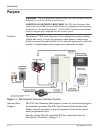
Figure 1-1 XW Automatic Generator Start Basic Function - - - - - - - - - - - - - - - - - - 1–2
Figure 1-2 XW Auto Generator Start Front Panel - - - - - - - - - - - - - - - - - - - - - - - - 1–5
Figure 1-3 XW Auto Generator Start Bottom Panel - - - - - - - - - - - - - - - - - - - - - - - 1–6
Figure 1-4 Wiring Harness- - - - - - - - - - - - - - - - - - - - - - - - - - - - - - - - - - - - - - - - 1–6
Figure 2-1 XW Auto Generator Start External Connections- - - - - - - - - - - - - - - - - - 2–3
Figure 2-2 XW Auto Generator Start Wiring Harness- - - - - - - - - - - - - - - - - - - - - - 2–6
Figure 2-3 Type 1 Connection Diagram - - - - - - - - - - - - - - - - - - - - - - - - - - - - - - - 2–9
Figure 2-4 Type 2 Connection Diagram - - - - - - - - - - - - - - - - - - - - - - - - - - - - - - - 2–10
Figure 2-5 Type 3 Connection Diagram - - - - - - - - - - - - - - - - - - - - - - - - - - - - - - - 2–11
Figure 2-6 Type 4 Connection Diagram - - - - - - - - - - - - - - - - - - - - - - - - - - - - - - - 2–12
Figure 2-7 Type 5 Connection Diagram - - - - - - - - - - - - - - - - - - - - - - - - - - - - - - - 2–13
Figure 2-8 Type 6 Connection Diagram - - - - - - - - - - - - - - - - - - - - - - - - - - - - - - - 2–14
Figure 2-9 Type 7 Connection Diagram (two-wire) - - - - - - - - - - - - - - - - - - - - - - - 2–15
Figure 2-10 Type 7 Connection Diagram (three-wire) - - - - - - - - - - - - - - - - - - - - - - 2–15
Figure 2-11 Type 8 Connection Diagram (two-wire) - - - - - - - - - - - - - - - - - - - - - - - 2–16
Figure 2-12 Type 8 Connection Diagram (three-wire) - - - - - - - - - - - - - - - - - - - - - - 2–16
Figure 2-13 Type 9 Connection Diagram - - - - - - - - - - - - - - - - - - - - - - - - - - - - - - - 2–17
Figure 2-14 Type 10 Connection Diagram - - - - - - - - - - - - - - - - - - - - - - - - - - - - - - 2–18
Figure 2-15 Type 11 Connection Diagram - - - - - - - - - - - - - - - - - - - - - - - - - - - - - - 2–19
Figure 2-16 Type 12 Connection Diagram - - - - - - - - - - - - - - - - - - - - - - - - - - - - - - 2–20
Figure 2-17 Type 13 Connection Diagram - - - - - - - - - - - - - - - - - - - - - - - - - - - - - - 2–21
Figure 2-18 External ON/OFF Switch and LED Wiring Diagram- - - - - - - - - - - - - - - 2–25
Figure 2-19 XW Auto Generator Start External Connections- - - - - - - - - - - - - - - - - - 2–26
Figure 2-20 Connecting the XW System Control Panel - - - - - - - - - - - - - - - - - - - - - 2–27
Figure 2-21 Verifying Power is Available - - - - - - - - - - - - - - - - - - - - - - - - - - - - - - 2–28
Figure 3-1 XW System Control Panel Navigation Buttons and XW System
Home Screen 3–2
Figure 3-2 Accessing the XW Automatic Generator Start Menu- - - - - - - - - - - - - - - 3–3
Figure 3-3 Changing Settings - - - - - - - - - - - - - - - - - - - - - - - - - - - - - - - - - - - - - - 3–4
Figure 3-4 XW Auto Generator Start Basic Menu Contents- - - - - - - - - - - - - - - - - - 3–5
Figure 3-5 XW Auto Generator Start Configuration Menu Contents - - - - - - - - - - - - 3–6
Figure 4-1 XW Auto Generator Start Home Screen - - - - - - - - - - - - - - - - - - - - - - - 4–2
Figures