


A
abbreviations and symbols iv
AC circuit breaker requirements 2–9
AC grounding requirements 2–7
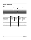
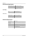
AC output voltage ratings A–2
AC wiring instructions 3–5
acceptable wire sizes A–6
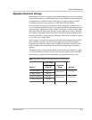
adjustable disconnect settings A–3
C
communication between multiple inverters 3–8
communications cabling 3–10
installing for multiple inverters 3–12
standard CAT 5 wiring 3–10
Customer Service
preparing to call WA–4
D
DC wiring instructions 3–3
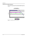
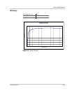
derating chart A–4
dimensions 2–11, A–6
display accuracy A–6
E
efficiency chart A–5
electrical specifications A–2
error messages and solutions 6–4
F
fault conditions and solutions 6–4
features and options 1–3
front panel display 1–3, 5–2
fault messages 5–7
normal operation messages 5–3
offline mode messages 5–5
reading messages 5–3
special messages 5–8
startup messages 5–3
G
general maintenance 6–3
ground clearance required for installation 2–4, 2–12
ground fault protection fuse 5–7
grounding requirements 2–7
GT- Vi e w 3–12
guidelines for matching PV array size to inverter input
2–7
H
humidity limits A–6
I
information about your system form WA–4
installation
grounding requirements 2–7
location concerns 2–4
mounting 2–13
options 2–2
overview 2–10
planning issues 2–2
preparing for 2–9
PV array requirements 2–5
routing wires 2–8
inverter
features and options 1–3
installation 2–10
model number WA–4
purchase date WA–4
purpose 1–2
serial number WA–4
L
LEDs, See status LEDs
lightning protection 2–8
M
maintenance, general 6–3
maximum power point tracking, See MPPT
mechanical specifications A–6
messages, See front panel display
model number WA–4
mounting bracket
installing 2–12
on backing support 2–15
on poles or rails 2–14
mounting the inverter
clearance requirements 2–12
Index