


Wiring the Inverter
3–8 975-0253-01-01
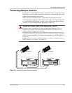
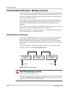
Communications Wiring for Multiple Inverters
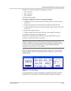
Communications wiring between multiple GT Inverters allows information about
each inverter and its associated PV array to be communicated between all of the
inverters in the system. Information about the entire system can be displayed on
any inverter LCD in the system.
For example, in a two-inverter system, if inverter #1 is producing 1500 W and
inverter #2 is producing 2000 W, both inverters display a total system power of
3500 W. The cumulative energy produced by both inverters that day is also
displayed.
You can still view information for an individual inverter in a system. See “To view
unit-specific screens in a multiple unit system:” on page 5–5.
Without communications wiring, each inverter in a system displays information
only for the unit and its associated PV array.
Xanbus Network Technology
GT Inverters are Xanbus-enabled devices. They use Xanbus (a communications
protocol developed by Xantrex) to communicate with other GT Inverters.
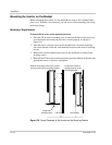
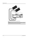
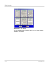
Network connections between inverters are laid out in a “daisy chain” pattern,
with each device on the network linked with separate lengths of cable, as shown in
Figure 3-6.
For more information on installing a Xanbus network, see the Xanbus System
Installation Guide, available at www.xantrex.com.
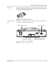
Figure 3-6
Daisy Chain Layout
CAUTION: Equipment damage
Connect only Xanbus-enabled devices.
Although the cabling and connectors used in this network system are the same as ethernet
connectors, this network is not an ethernet system. Equipment damage may result from
attempting to connect Xanbus to different systems.
Xanbus-enabled
Device 1
Xanbus-enabled
Device 2
Xanbus-enabled
Device 3
Terminator
Terminator