


Installation
2–12 975-0253-01-01
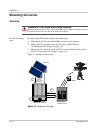
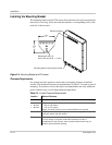
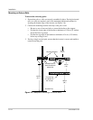
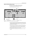
Installing the Mounting Bracket
The mounting bracket for the GT Inverter allows the unit to be easily mounted and
removed for servicing. It has one hook that matches a corresponding hook on the
back side of the inverter.
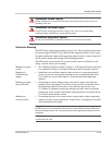
Clearance Requirements
For optimal and safe operation, ensure there is adequate clearance around the
inverter. The minimum clearance recommendations in Table 2-2 assume a vertical
mounting. If clearances are less than these recommendations are used, additional
power reduction may occur at high ambient temperatures.
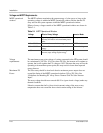
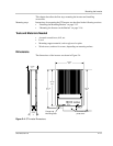
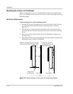
Figure 2-5
Mounting Bracket and GT Inverter
23.8 cm
9.4"
18.3 cm
7.2"
Mounting slots for securing the inverter
Mounting flanges
Rectangular slots × 8:
8 mm × 30 mm (5/16" × 1-3/16")
Table 2-2
Inverter Clearance Requirements
Location Minimum Clearance
Above 30 cm (12 inches)
Below:
• Inverter
• Bracket
Outdoors:
• 100 cm (39 inches)
• 130 cm (51 inches)
Indoors: the same clearances are recommended but not required.
In front Sufficient room to allow for easy access to read the display and to prevent
accidental contact with hot surface.
On sides
Units can be mounted side by side with no clearance between them, but
15 cm (6 inches) of clearance around the outermost two units is
recommended. In hot climates, some clearance between units may be
needed to prevent thermal derating.