


Wiring the Inverter
3–6 975-0253-01-01
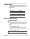
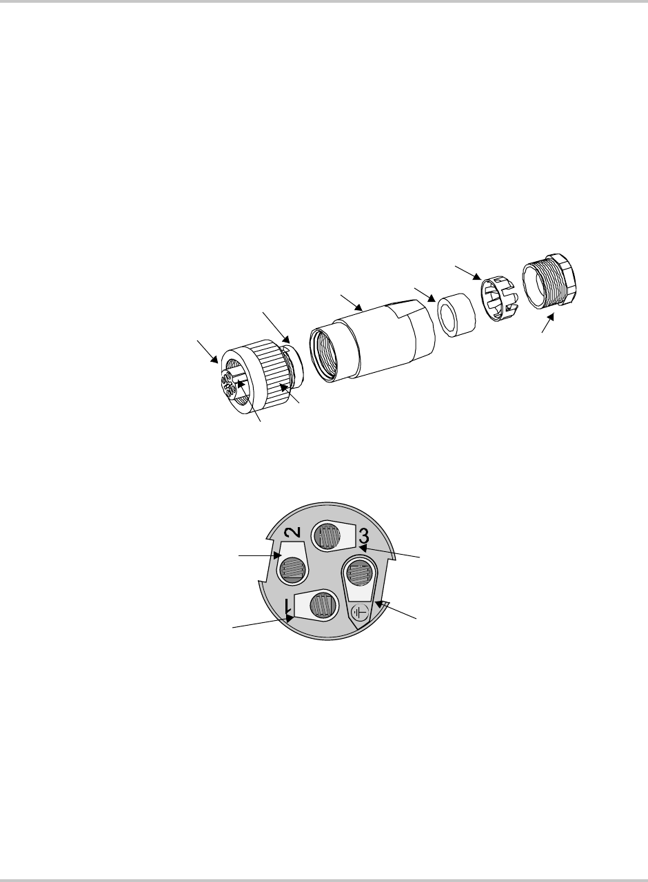
5. On the female terminal, connect the protective earth wire to the terminal
marked with the ground ( ) symbol. See Figure 3-4.
6. Connect the neutral wire to the terminal marked with 1.
7. Connect the Phase L wire to the terminal marked with 2.
Terminal 3 is not used.
8. After ensuring all the wires are tightened in their terminals, screw the casing
onto the female terminal.
9. Replace the remaining components of the female cable connector, ensuring a
tight seal.
10. Tighten the pressing screw.
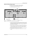
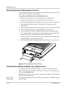
Connecting to the GT Inverter
To connect the AC connector to the GT Inverter:
1. Line up the notch on the female AC cable connector with the connector on the
GT Inverter.
2. Insert the AC cable connector into the connector on the GT Inverter.
3. Secure the connector by turning the outer ring.
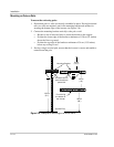
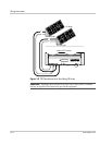
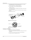
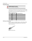
Figure 3-3
AC Connector (female)
Figure 3-4
AC Connector Terminals
Female terminal
Shell
Seal
Pinch ring
Pressing screw
Outer ring
Notch
AC connector terminals
(see Figure 3-4)
Protective Earth
(ground) wire
Not used
Neutral wire
Phase L wire