


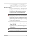
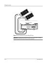
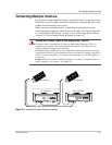

Communications Wiring for Multiple Inverters
975-0253-01-01 3–11
Purchasing Network Components
Consult your system designer to determine what network components will be
needed for your specific installation. Table 3-2 provides a partial list of network
components and part numbers. Pre-made cables are available in standard lengths
from 3 feet to 75 feet.
Call your dealer or visit www.xantrex.com for information on purchasing
network components.
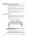
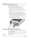
Guidelines for Routing the Network Cables
To ensure maximum performance of your network, follow these guidelines when
routing the network cables. Route the cables before installing Xanbus-enabled
devices.
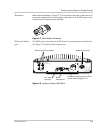
• Route the cables away from sharp edges that might damage the insulation.
Avoid sharp bends in the cable—no less than a 10 cm (4 inch) radius.
• Allow for some slack in the cable tension.
• Keep the alignment of wire pairs inside the sheath as straight as possible.
• Allow separation between data and power cables (data cables should only
cross a power cable at right angles).
• Do not staple the cable with metal cable staples. Use the appropriate hardware
fasteners to avoid damage to the cable.
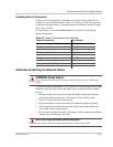
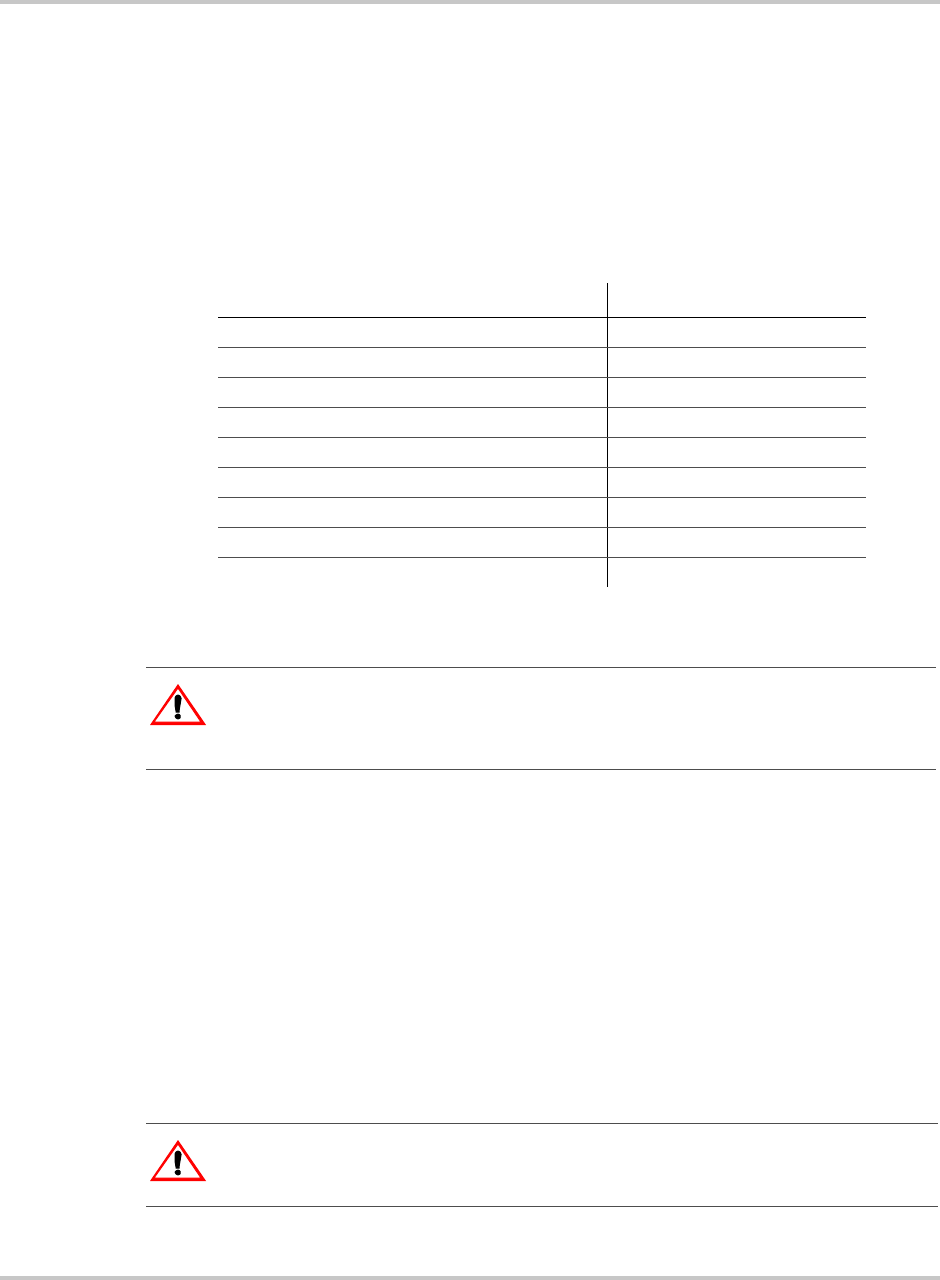
Table 3-2
Network Components and Part Numbers
Network Component Part Number
Network termination — Male (2 per pack) 809-0901
Network cable 3 ft. (0.9 m) 809-0935
Network cable 5 feet (1.5 m) 809-0936
Network cable 7 feet (2.0 m) 809-0937
Network cable 10 feet (3.0 m) 809-0938
Network cable 14 feet (4.3 m) 809-0939
Network cable 25 feet (7.6 m) 809-0940
Network cable 50 feet (15.2 m) 809-0941
Network cable 75 feet (22.9 m) 809-0942
:
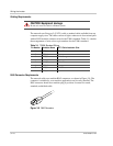
WARNING: Shock hazard
Do not route the network cables in the same conduit or panel as the AC and DC power
cabling.
CAUTION: Unpredictable device behavior
Do not connect one end of the network to the other to make a ring or loop.