


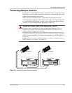

Connecting Multiple Inverters
975-0253-01-01 3–7
Connecting Multiple Inverters
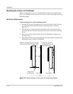
For installations with multiple inverters, a separate PV array is required for each
GT Inverter unit. The output of each GT Inverter feeds a separate dual-pole circuit
breaker in the main utility service panel.
When connecting multiple inverters, complete the wiring and perform the
commissioning procedure for each inverter one at a time. For wiring instructions,
see “Connecting the DC Wiring” on page 3–2 and “Connecting the AC Wiring”
on page 3–5. For the commissioning procedure, see page 4–2.
WARNING: Shock hazard and equipment failure
If inverters “share” more than one PV array, an input current difference of over 1 A
between arrays can cause short circuit failure in each inverter. This failure will also
generate hazardous voltages around each unit.
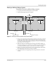
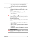
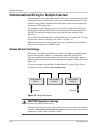
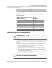
In multiple inverter installations, it is very important to ensure each inverter is correctly
connected to its own PV array(s) and that no wires are crossed. For example, connect PV1
positive (+) and PV1 negative (–) to inverter 1 and PV2 positive (+) and PV2 negative (–)
to inverter 2.
Do not connect PV1 positive (+) and PV2 negative (–) to inverter 1 and PV2 positive (+)
and PV1 negative (–) to inverter 2. See Figure 3-5.
Figure 3-5
Improper multiple inverter connections
–
–
+
+
PV Array #1 PV Array #2
GT Inverter #1
GT Inverter #2