


Assembly 23
MAN0458 (9/23/2005)
ASSEMBLY INSTRUCTIONS
DEALER SET-UP INSTRUCTIONS
Assembly of this chipper is the responsibility of the
Woods dealer. If should be delivered to the owner
completely assembled, lubricated, and adjusted for
normal chipping conditions.
Assembly will be easier if parts are aligned and loosely
assembled before tightening hardware. Recommended
torque values for hardware are located in the Bolt
Torque Chart, page 35.
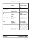
Complete check lists on page 27 when you have
completed the assembly.
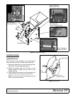
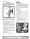
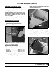
INSTALL 3-POINT HITCH PINS
1. Attach 3-point hitch pins to the chipper frame using
nuts and washers supplied with each pin.
2. Torque pins to 474 lbs-ft.
Figure 11. 3-Point Hitch Pin Installed, Left Pin Shown
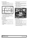
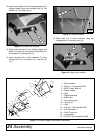
INSTALL CHIPPER HOPPER
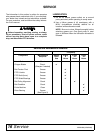
NOTE: Once all parts are installed and aligned torque
hardware to specifications listed below.
3/8 NC x 1 . . . . . . . . . . . . . . . 35 lbs-ft (47 N-m)
5/16 NC x 1 . . . . . . . . . . . . . . . 19 lbs-ft (26 N-m)
5/16 NC x 3/4. . . . . . . . . . . . . . 19 lbs-ft (26 N-m)
1. Attach chipper hopper to the chipper housing using
four carriage bolts (2), flat washers (1), and lock
nuts (3). See Figure 12 and Figure 17.
NOTE: Make sure the heads of the carriage bolts
are on the inside of the chute.
Figure 12. Chute and Hinge Installed
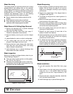
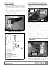
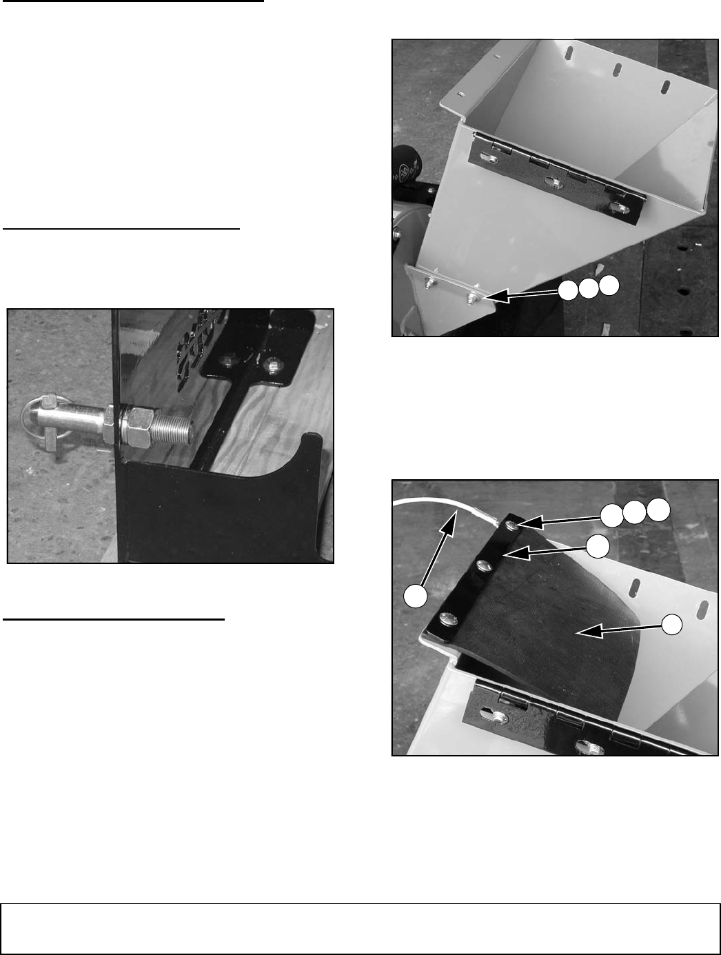
2. Attach rubber flap (8) to the chute flange using flap
retainer strap (9), three carriage bolts (12), flat
washers (13), and lock nuts (14). Attach lanyard
(10) between the chute flange and washer (13)
farthest from the hinge.
Figure 13. Rubber Flap and Lanyard Installed
3
2
1
DP4
10
DP5
12
9
8
13
14