


Service 19
MAN0458 (9/23/2005)
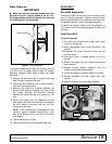
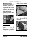
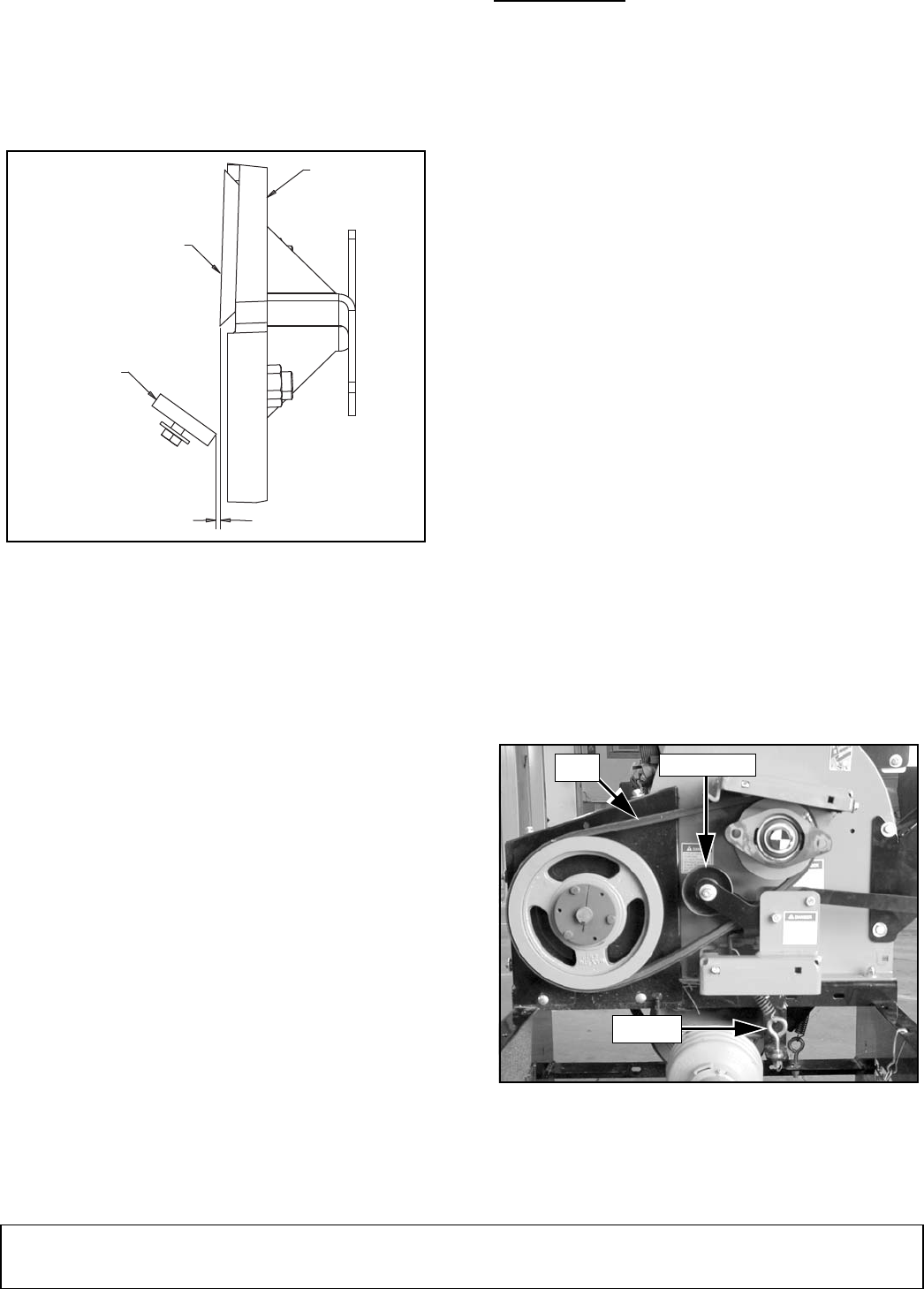
Blade Clearance
IMPORTANT
■ Make sure that the clearance between the chip-
ping anvil and ALL chipper blades is set to 1/16".
All chipper blades should be rotated until even with
the chipping anvil and measured.
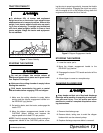
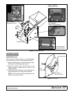
Figure 7. Anvil Clearance
The chipper blades should clear the chipping anvil by
1/16 inch. Anvil is located directly under the chipper
discharge opening. Follow steps to adjust the blade
clearance:
1. Remove the discharge cap or optional discharge
tube for easier access to the anvil.
2. Rotate the disk assembly until a chipper blade is
even with the chipping anvil.
3. Measure the amount of clearance between the
chipper blade and the chipping anvil from inside
the chipper housing. The minimum distance
between the blade and the anvil should be 1/16
inch.
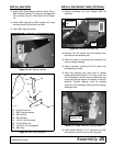
4. Adjust the chipping anvil by loosening the 5/16
bolts holding the anvil to the disk cover and sliding
the anvil inward or outward until the 1/16 inch
clearance is achieved.
NOTE: If the chipping anvil is damaged or worn
unevenly, remove hardware holding anvil to the
disk cover. Rotate anvil to use one of the other
three edges.
5. Tighten hardware to 19 lbs-ft.
6. Install discharge cap or optional discharge tube.
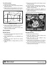
DRIVE BELT
Drive Belt Adjustment
Check the condition of the drive belt(s) annually or after
every 25 hours of operation. Replace cracked, frayed.
worn or stretched belt. Only replace drive belt with orig-
inal banded type belt. Do not use single type belts.
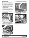
To adjust belt: tighten eyebolt until belt deflection is
7/16" when a 20-lb load is placed against the belt. See
Figure 9.
Front Drive Belt
Front Belt Removal
1. On a hard level surface lower chipper with 3-point
lift arms to the ground.
2. Move engagement lever to the RELEASE (up)
position.
3. Disconnect drive shaft, 3-point lift arms, and top
link from tractor.
4. Place drive shaft in storage position up off the
ground.
5. Remove belt shield from the chipper housing and
save hardware.
6. Remove bearing support weldment from the
chipper housing and save hardware.
7. Loosen the eyebolt to release tension on the belt.
8. Remove hardware and idler pulley from idler
bracket.
9. Remove old belt from around both sheaves.
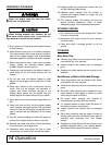
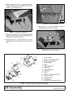
Figure 8. Front Belt Drive Assembly
1/16"
Chipper Blade
Anvil
Disk
LA4
Idler Pulley
Belt
Eyebolt
DP2