


WARNING! To prevent personal injury or property
damage, do not start the engine until all assembly
steps are complete and you have read and
understand the safety and operating instructions in
this manual.
Resommended Tools for Assembly
⁄” open-end wrench (1)
⁄” open-end wrench (2)
⁄” open-end wrench (2)
⁄” open-end wrench (1)
⁄” open-end wrench (1)
Flat blade screwdriver (1)
Scissors (to trim plastic ties)
Tire pressure gauge (1)
4-⁄” high wood block to prop machinne
Contents of Hardware Pack
26 oz. Bottle SAE 30W Oil (1)
Clutch Pawl Spring (1)
Belt Adjusting Tool (1)
Plastic Cable Ties (2)
Curved Head Screw, ⁄-20 x 2 (1)
Flanged Lock Nut, ⁄-20 (1)
Pan Head Screw, #10-32 x ⁄ (1)
The following parts (electric start models only), packaged
separately.
Nuts, ⁄-20 for battery terminals (2)
Screws, ⁄-20 x ⁄ for battery terminals (2)
Keys in ignition switch (2)
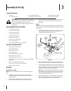
Assembly
Unpacking Instructions
NOTE: Do not severely bend any of the control cables on the
tiller.
The tiller is heavy. Do not attempt to remove it from
the shipping platform until instructed to do so in these
assembly steps.
Remove all unassembled parts from the carton. The
hardware bag is included in your literature packaging.
•
•
•
•
•
•
•
•
•
•
•
•
•
•
•
•
•
•
•
•
1.
2.
Check that you have the items listed above (contact your
local dealer or the Factory if any items are missing or
damaged).
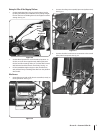
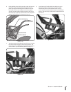
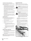
Handle
NOTE: When disassembling the handlebar assembly, keep the
left-side clamp and ratchet separated from the right-side clamp
and ratchet.
Disassemble the handlebar assembly. To do this, remove
the height adjustment lever by turning the lever in a
counterclockwise direction. See Fig. 3-1.
Place the handlebar ends on either side of the base, with
the wire harness toward the rear of the base See Fig. 3-1.
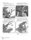
Install the height adjustment lever through the right-side
clamp, handlebar end, ratchet, and base; then out through
the left-side ratchet, handlebar end, and clamp. See Fig.3-1.
Secure with the nut, but do not fully tighten.
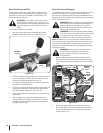
NOTE: Do not force the height adjustment lever through
the handlebars. The interlock wires may be blocking the
lever and could be damaged. You may gently move the
wires aside if this condition occurs.
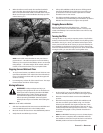
Raise the handlebars to one of two height settings and
tighten the height adjustment lever. Also, make sure all
other mounting hardware is securely tightened.
3.
1.
2.
3.
4.
Contents of Carton
One Tiller • One Handlebar Support• One Handlebar Assembly•
One Hardware Pack• One Wheels/Tines PTO Lever• One Operator’s Manual•
Height
Adjustment
Lever
Right
Clamp
Handlebars
Right
Ratchet
Left
Ratchet
Base
Left
Clamp
Nut
Wire Harness
Base
Bolt
Figure 3-1
Assembly & Set-Up
3
6