


For dipsticks With ‘Check Cold’ Marking (Cold means 2 hours
have passed since the tiller was used.)
Move the tiller to level ground.
Pull the Depth Regulator Lever back, then push it down all
the way (to engage its top notch).
Place a sturdy support under the engine to prevent the
tiller from tilting too far.
Now slide three pieces of 2” x 4” lumber underneath the
drag bar — raising the drag bar about 4-⁄” above ground.
This elevation allows an accurate “cold” gear oil reading .
Wait two hours with tiller elevated (allow more time if
temperature is below 40ºF).
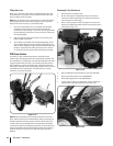
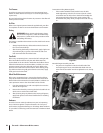
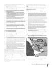
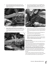
Loosen and remove transmission dipstick on the back of
the tine shield. See Fig. 6-7. Wipe it clean with a rag.
Hold the dipstick so its markings face to rear of tiller. Lower
it straight down into the sump hole to touch the drive shaft
inside. See Fig. 6-7. Don’t force or try to thread it back in; an
incorrect reading will result.
Remove the dipstick and check the oil level. It should be
anywhere within the crosshatched area or even slightly
above the Max marking. If correct, replace the dipstick and
remove the boards used as props.
If the oil level was low, gear oil must be added before using
the tiller. See Adding or Changing Gear Oil the next page.
For Dipsticks With Hot/Cold Markings
Move the tiller to level ground.
Pull the Depth Regulator Lever back, then push it down all
the way (to engage its top notch).
Place a sturdy support under the engine to prevent the
tiller from tilting too far.
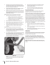
Cold reading (preferred method): (Two hours has passed
since the tiller was used.) Place a 2” x 4” board (on edge)
under the drag bar — raising the tiller and drag bar about
3-⁄” above ground. Hot reading: (Tiller was operated for
more than 30 minutes within the past hour.) Do not use the
wood prop to elevate the tiller.
Follow Steps 4, 5 and 6 given for the other dipstick type.
Remove the dipstick and check the level. It should be
within or above the “Cold” range marking if taking a cold
reading. If taking a hot reading, the level should be within
or slightly above the “Hot” range.
If the level is incorrect, see Adding or Changing Gear Oil.
Adding or Changing Gear Oil
For partial fill-ups (just a few ounces or less), use SAE 140, SAE
85W-140, or SAE 80W-90 weight gear oil with an API rating of
GL-4 or GL-5. For full replacement, use SAE 140 or SAE 85W-140
gear oil with an API rating of GL-4 only. (At the factory, SAE 85W-
140 weight gear oil is used.)
NOTE: Do not use automatic transmission fluid or engine oil.
They are too light in weight and will result in transmission
damage.
NOTE: The gear oil does not need to be changed. Do so only if
you know, or suspect, it is contaminated with dirt, sand or other
foreign particles.
1.
2.
3.
4.
5.
6.
7.
8.
9.
1.
2.
3.
4.
5.
6.
7.
Gear oil is available at authorized dealers and most service
stations, power equipment centers, or farm/heavy equipment
outlets.
Capacities: The Power Unit transmission holds approximately
60 ounces and the Tine Attachment transmission holds
approximately 12-⁄” ounces.
Adding Gear Oil to the PTO Power Unit Transmission
Do steps 1 and 2 of Checking the Power Unit Oil Level.
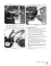
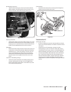
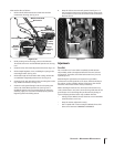
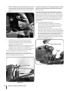
Using a ⁄” wrench (or socket), remove the bolt securing
the handlebar base to the top of the transmission (prop
the handlebars first to prevent them from falling). Then,
unplug the Forward Interlock wire harness receptacle at
the bottom of the handlebars. Set the handlebar base and
bolt aside on a clean surface. The bolt hole in the top of the
transmission is the gear oil fill hole. See Fig. 6-7.
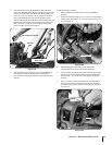
Slowly pour gear oil through a clean funnel into the
transmission. Stop when gear oil begins to flow from the
oil level check hole on the left side of the transmission. See
Fig. 6-7.
Reinstall the oil level check plug. Tighten it securely.
Reinstall the handlebars using the mounting bolt
previously removed. Align the handlebars so they point
straight backwards, not at an angle. Then tighten the
mounting bolt securely.
Reconnect the Forward Interlock wire harness to the
receptacle. Be certain it’s secure.
Test the operation of the Forward Interlock Safety System.
See Forward Interlock System on the next page.
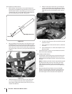
Draining and Filling the PTO Power Unit Transmission
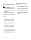
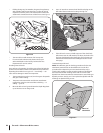
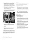
Place a shallow pan under the transmission gear oil drain
plug. See Fig. 6-8.
Remove the oil level check plug with a ⁄” wrench. This
vents the transmission for faster oil draining.
1.
2.
3.
4.
5.
6.
7.
1.
2.
Oil Level Check Plug
Gear Oil
Fill Hole
Gear Oil
Drain
Figure 6-8
29sectiOn 6 — Maintenance & adjustMents