


Using the ⁄” wrench, remove the drain plug. The gear
oil will drain quite slowly since it is thick. After about two
quarts have drained, tilt the tiller forward so any oil at the
rear of the transmission will drain out.
Clean the drain plug threads, put non-hardening gasket
sealant on the threads, and reinstall the plug.
Refill the transmission with the correct amount of gear oil
before operating the tiller again. When oil seeps from the
oil level check hole, the right amount of gear oil has been
added. Replace all plugs.
Adding Gear Oil to the Tine Attachment Transmission
Select the right Depth Regulator Lever setting:
If filling an empty transmission, raise the Depth
Regulator Lever so tines are on the ground.
If topping off the gear oil, move Depth Regulator
Lever down to engage its top notch.
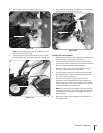
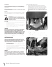
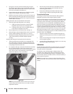
Remove dipstick from tine attachment. See Fig. 6-6.
Slowly add gear oil in the dipstick hole. Add ⁄-ounce at a
time to avoid overfilling. It takes about 12-⁄ ounces.
Take dipstick readings frequently. Stop when oil reaches
“Cold” range marking on dipstick. Replace dipstick
securely.
Draining and Filling the Tine Attachment Transmission
The tine attachment transmission is not equipped with
an oil drain plug. To drain just a small amount of gear oil,
remove the dipstick and tilt the attachment forward, first
uncoupling it from the Power Unit.
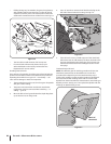
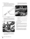
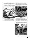
For complete drainage, remove the left-side tine assembly
(See Tine Replacement in the Service section.), then
remove just one of the lower screws from the tiller housing
cover. See Fig. 6-9. To speed drainage, remove the tine
attachment dipstick to vent transmission.
NOTE: If you find a plastic washer on the cover screw you
remove, discard the washer. There is no need to install a
replacement washer.
3.
4.
5.
1.
a.
b.
2.
3.
4.
1.
2.
Once all the gear oil has drained, reinstall the housing
cover screw securely (first coat its threads with non-
hardening gasket sealant).
Be certain to refill the transmission with the correct
amount of gear oil before operating the tiller again.
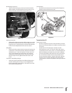
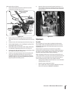
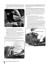
Forward Interlock System
The wiring circuit for the Forward Interlock Safety System is
designed to ground out the engine’s ignition system.
There are three switches in the circuit which, when open, let the
engine run. One switch is on the neutral plunger tab of the cast
iron motor mount. This switch is open whenever the Wheels/
Tines/PTO Drive Lever is in NEUTRAL or REVERSE positions. The
other two switches are located inside the handlebars, directly
above the two Forward Interlock Levers. The switches are wired
so when squeezed (open) the engine will run. There is a fourth
switch located in the wiring harness connector on the top, right
side of the transmission cover. It warns you if the connection is
not mated by not letting the engine run while the Wheels/Tines/
PTO Drive Lever is in FORWARD.
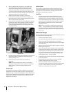
A broken or disconnected wire could let the engine run
without you having to press one of the Forward Interlock
Levers.
A bare wire touching tiller or engine metal could ground
out the engine’s ignition.
A switch that has failed allows the engine to run. Or it may
prevent the engine from running.
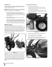
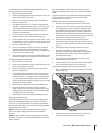
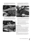
Lubrication
Proper lubrication of the tiller’s mechanical parts is an essential
part of good maintenance. Lubrication should be done after
every ten (10) hours of operation.
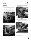
Use ordinary motor oil (#30 weight or lighter) where oil is
specified. Use a quality grease with a metal lubricant where
grease is recommended (regular grease is acceptable). Do not
over lubricate. If there is a build-up of dirt, remove the build-up
and re-apply oil or grease.
NOTE: Do not allow oil or grease to contact the pulleys, drive
belt or reverse disc. This can cause the belt or disc to slip on the
pulleys.
3.
4.
1.
2.
3.
Figure 6-9
30 sectiOn 6— Maintenance & adjustMents