


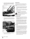

Starting Electric Start Engine with Recoil Starter
You may, at some point, have to start an electric start engine
with the recoil starter rope. Before attempting to do so, perform
the following applicable steps:
If you suspect the battery charge is weak, and there is no
visible damage. Disconnect the cables from the battery
and clean both cable terminals, and the battery posts
in accordance with the instructions provided in the
Maintenance & Adjustments section. Reconnect the cables
and securely tighten to the battery posts. The engine will
recharge the battery if the battery is still good.
If you suspect the batter is “dead”, or if the battery is
damaged, disconnect, and remove it. Have it checked by a
qualified technician.
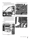
If the battery has been removed, wrap the cable terminals
at the end of the positive cable with electrical tape and
secure the cable to the battery bracket. This will prevent
electrical discharge.
Before pulling the recoil starter rope, turn the keyswitch
to the RUN position. Move the Throttle Lever away from
the STOP position and set the choke as applicable. See the
Engine Operator’s Manual.
Cold Weather Operation
When temperatures fall below 40º F, do the following steps to
protect your engine and transmission from damage:
Refer to the Engine Operator’s Manual for the motor oil
specifications for cold weather operation.
Use winter blend gasoline.
Warm the engine up before putting it under a load.
Use the correct weight gear oil in the PTO Power
transmission.
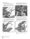
Warm up the transmission gear oil as follows:
With the engine running, move the Wheel Speed
Lever to FREEWHEEL (then block the wheels so they
can’t roll).
Put the Tines/PTO Clutch Lever into DISENGAGE,
then squeeze one of the Forward Interlock Levers
and shift the Wheels/Tines/PTO Drive Lever to
FORWARD.
If the wheels are frozen to the ground, melt the ice with
warm water.
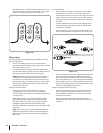
Stopping the Engine and the Tiller
To stop the wheels and tines, move the Wheels/Tines/PTO
Drive Lever into NEUTRAL position and then release both
Forward Interlock Levers.
Move the engine Throttle Lever to the STOP position. Then
on electric start models, turn the key to OFF. Remove the
key for safekeeping.
NOTE: The engine may have a separate Throttle Control Lever
and ON/OFF switch on the engine. These controls can also be
used to stop the engine. See the Engine Operator’s Manual for
information specific to your engine.
•
•
•
•
1.
2.
3.
4.
5.
a.
b.
6.
1.
2.
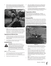
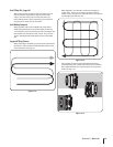
Engaging the Drive & Tines
NOTE: This is a traditional standard-rotating-tine (SRT) tiller
with forward rotating tines. It operates in a completely different
manner than counter-rotating-tine (CRT) tillers, or from front-tine
tillers.
WARNING! To help avoid personal injury, be aware
that the tiller can unexpectedly bounce up or jump
ahead and propel away from you if the tines strike
hard or frozen ground, or buried obstacles like large
stones, roots or stumps.
Start the engine and gradually increase the engine speed
to FAST.
Test the Forward Interlock Safety System. See the Forward
Interlock System in the Maintenance & Adjusments section
for more information.
WARNING! The Forward Interlock Safety System is
designed for the operator’s safety. Do not
disconnect or attempt to defeat the purpose of the
system. If the system malfunctions, immediately
contact your local authorized dealer or the TROYBILT
Technical Service Department for assistance. Do not
use the tiller or the PTO power feature until the
Forward Interlock Safety System is functioning
properly.
When practicing, set the Depth Regulator Lever to Travel
position. Otherwise, set the Depth Regulator Lever to a
desired depth.
Move Tines/PTO Clutch Lever to ENGAGE position if you
want the tines to turn. If practicing, leave in DISENGAGE.
NOTE: Do not move Tines/PTO Clutch Lever to ENGAGE
unless Wheels/Tines/PTO Drive Lever is in NEUTRAL. Tiller
damage may occur.
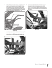
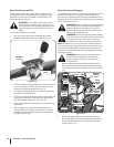
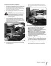
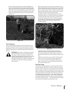
To move the tiller forward and engage the tines, squeeze
and hold either Forward Interlock Lever against the
handlebar grip (See Fig. 4-2), then move the Wheels/Tines/
PTO Drive Lever down to FORWARD position.
1.
2.
3.
4.
5.
Figure 4-2
14 sectiOn 5— OperatiOn