


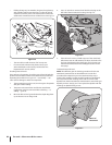

How to Measure the Belt Tension
Before taking a measurement, be sure the linkages and
pivot points on the Wheels/Tines/PTO Drive Lever are clean
and lubricated. If there is any binding, you won’t get true
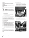
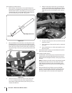
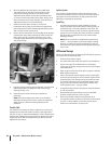
measurements. Also, you’ll need the belt adjustment tool
you received with your new tiller. See Fig. 6-12.
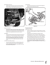
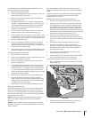
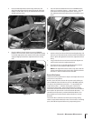
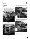
Move the Wheels/Tines/PTO Drive Lever fully down to the
FORWARD position. The clutch roller at the bottom of the
lever should be positioned underneath the belt adjustment
block. See Fig. 6-13. Don’t let the clutch roller move during
the next few steps. If it moves, you’ll get a false belt tension
reading.
The belt tension is correct if the front of the clutch roller
is ⁄”-to-⁄” away from the face of the upright bracket
that holds the adjustment block in place. See Fig. 6-13. To
measure this distance:
1.
2.
3.
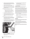
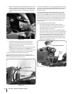
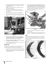
Without moving the clutch roller, try inserting the
⁄”-thick, slotted end of the belt adjustment tool in
between the roller and the upright bracket. The flat
edge of the tool must be facing the roller. See Fig.
6-14.
If only the slotted portion of the tool will fit, the belt
tension is correct.
If the slotted part of the tool will not fit in, the belt is
too loose.
If the full thickness (⁄”) of the tool easily fits in, the
belt is too tight.
If the belt tension is correct, move the Wheels/Tines/PTO
Drive Lever back to NEUTRAL.
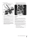
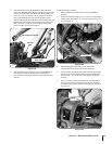
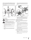
How to Adjust the Belt Tension
As described in the following steps, the drive belt tension
is adjusted by moving the adjustment block up or down.
Moving it down will tighten the belt; moving it up loosens
the belt.
NOTE: The distance the block moves approximately equals
the distance the roller moves. In most cases, the clutch
roller will not have been very far out of position, so the
adjustment block will only need to be moved slightly (up
or down).
Move the Wheels/Tines/PTO Drive Lever to NEUTRAL
position. The clutch roller will come to rest anywhere on
the face of the belt adjustment block, depending upon
drive belt length and current belt tension adjustment.
a.
b.
c.
d.
4.
1.
2.
Slotted End
Figure 6-14
7.94 mm
⁄”
⁄”
6.35 mm
Belt Adjustment Tool
Figure 6-12
⁄” - ⁄”
Figure 6-13
32 sectiOn 6— Maintenance & adjustMents