


Engine Throttle Lever and Cable
For shipping purposes, the throttle cable, together with the
throttle lever, is wound around the engine. Carefully unwind
the cable. If the throttle control label is covered with a clear
protective coating, peel it off.
WARNING! To avoid electric shock from a short
circuit (electric start tillers only), never allow the
throttle cable to touch the battery. Route the cable
below the battery, on the outside of the battery
holder.
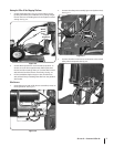
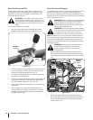
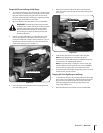
To attach the throttle lever and cable:
Run the throttle cable up the inside edge of the right
handlebar and position the lever as shown in Fig. 3-13.
From the outside of the handlebar, insert the curved head
screw, through the handlebar and the center hole in the
throttle lever mounting bracket. See Fig. 3-13.
Loosely install the flanged lock nut and move the throttle
lever back to the STOP position.
From the lever side of the bracket, thread a pan head screw
through the small hole in the throttle lever bracket and
into the handlebar. Tighten the screw securely.
Securely tighten both the flanged lock nut and the curved
head screw.
Use two plastic ties to secure the throttle cable to the
right handlebar in two places. Loop each tie around the
handlebar and cable (serrated side faces in) and pull the
ties tight. Trim the ends.
1.
2.
3.
4.
5.
6.
Electric Start System (If Equipped)
The following steps explain how to install and charge the battery
on electric start tillers. For your safety, follow all steps and
observe all accompanying safety messages. The Maintenance &
Adjustments section contains other general battery maintenance
and recharging instructions.
WARNING! Battery produces explosive gases. Keep
away sparks, flames, and cigarettes. Ventilate area
when charging or using battery in an enclosed
space. Make sure battery vent tube is always open
after battery is filled with acid.
WARNING! Remove metal jewelry before working
near the battery or near the electrical system. Failure
to comply may cause a short circuit, resulting in
electrical burns, a shock, or battery gas explosion.
NOTE: If the battery is put into service after the date shown on
the top of the battery, charge for a minimum of one hour at 6-10
amps. Refer to the Maintenence & Adjustments section of this
manual for more detailed instructions regarding proper battery
charging procedure.
WARNING! Never jump start the battery with a
vehicle battery or charging system. This may
produce a battery explosion, causing acid or
electrical burns.
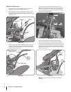
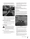
Before installing the battery and its hold-down clamp,
insert the plastic wire harness receptacle into the prongs
of the keyswitch located on the hold-down clamp. See Fig.
3-14.
Remove the ignition keys from the keyswitch and store
them safely away. Do not insert the key into the keyswitch
until you complete this section and read the Operation
section. See Fig. 3-14.
1.
2.
Pan Head
Screw
Curved Head
Screw
Figure 3-13
O
IL
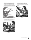
Screw
Negative
Battery
Post
Negative
Battery
Cable
Black
Rubber
Boot
Nut
Keyswitch
Harness
Receptacle
Selenoid
Black
Rubber
Boot
Positive
Battery
Cable
Positive
Battery
Post
Figure 3-14
10 sectiOn 2— asseMbly & set-up