


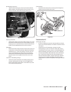
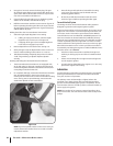
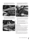
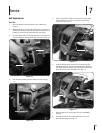

Insert the belt adjustment tool through the hole in the
side of the adjustment block, spacing the ends of the tool
equally on both sides. See Fig. 6-15. Rotate the tool so the
slotted end faces down.
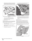
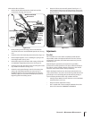
Place the Wheels/Tines/PTO Drive Lever in FORWARD
position. The arms of the clutch control yoke will be resting
on the belt adjustment tool and the clutch roller should be
engaged slightly beneath the adjustment block. See Fig.
6-16.
3.
4.
Adjustment Block
Belt Adjustment Tool
Figure 6-15
Clutch Roller
Adjustment Block
Figure 6-16
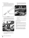
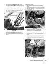
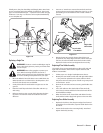
Use one hand to hold the drive lever in FORWARD while
using a ⁄” wrench to loosen — don’t remove — the bolt
at the back of the belt adjustment block. See Fig. 6-17.
The adjustment block should be free to move either up or
down.
Push the drive lever down if the belt needs tightening. Pull
the lever up if the belt needs to be loosened. Hold the drive
lever in place and tighten the bolt in the adjustment block
firmly.
Let go of the drive lever and remove the belt adjustment
tool from the hole in the adjustment block.
Check the tension on the belt by following the previous
instructions “How to Measure Belt Tension.”
NOTE: If the adjustment block is all the way down and the
measurement between the clutch roller and the bracket is
less than ⁄”, then a new drive belt is needed.
Reverse Drive System
These instructions explain how to inspect and adjust the various
reverse drive components.
But first, here’s how the reverse drive system works. When you
raise the Wheels/Tines/PTO Drive Lever up in REVERSE position,
this lowers the rubberized reverse disc — it’s attached to the
engine drive pulley — until this rotating disc contacts the
transmission drive pulley. The friction between the rotating
reverse disc and the transmission pulley causes the transmission
drive shaft to be powered in a counterclockwise direction — as
viewed from the operator’s position behind handlebars. The
drive shaft then turns the wheels and tine shafts in a reverse
direction.
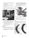
The reverse disc is made of steel with a special, long-lasting
rubber compound bonded to the disc rim. Since this is a wearing
part, it should be inspected after every 30 operating hours.
5.
6.
7.
8.
Bolt
Drive Lever
Figure 6-17
33sectiOn 6 — Maintenance & adjustMents